Compact radio frequency transmitting and receiving antenna and control device employing same

a radio frequency transmitting and receiving antenna and control device technology, applied in the direction of loop antennas, radiating element structural forms, instruments, etc., can solve the problems of relatively large antennas of prior art devices, relatively high cost of planar antennas, and relatively high cost of manufacture, so as to reduce the amount of insulation needed, less expensive to make, and small in size

Active Publication Date: 2005-12-22
LUTRON TECH CO LLC
View PDF24 Cites 146 Cited by
  • Summary
  • Abstract
  • Description
  • Claims
  • Application Information

AI Technical Summary

Benefits of technology

[0012] It is a further object of the present invention to provide an antenna as part of a lighting control device which is less expensive to make than the prior art planar antenna and which is smaller in size than the prior art planar antenna.
[0013] Yet still a further object of the present invention is to provide an antenna for a lighting control device whose radiating part is isolated from the AC line, thereby reducing the amount of insulation necessary to protect the user.
[0014] It is yet still a further object of the present invention to provide an antenna of compact design that provides a substantially isotropic radiation pattern, that is, a radiation pattern that is substantially the same at a defined distance from the antenna.
[0015] It is yet still a further object of the present invention to provide an antenna that is easily tunable, has a broader potential frequency range and is made from readily available materials.
[0016] It is yet still a further object of the present invention to provide such an antenna that has flexibility so that it is useful in different products and, in particular, useful in different control units of an RF lighting control system, for example, master unit, repeater and local lighting control unit.

Problems solved by technology

One of the problems with the prior art antenna is that it is relatively expensive to make, requiring inductive patterns disposed on the printed circuit board determining the frequency of resonance.
These planar antennas are somewhat expensive to manufacture.
In addition, the antenna of the prior art device is relatively large in size, being substantially coextensive with the electrical box opening.
Furthermore, the prior art device requires substantial insulation because the antenna is connected to the AC line (or “line voltage”) and is thus at the same electrical potential.
Because the planar antenna is relatively large and because it is electrically connected to the line voltage of the dimmer, more insulation is needed when using the planar antenna, thus increasing the cost of the dimmer.

Method used


Image

  • Compact radio frequency transmitting and receiving antenna and control device employing same
  • Compact radio frequency transmitting and receiving antenna and control device employing same
  • Compact radio frequency transmitting and receiving antenna and control device employing same

Examples


Embodiment Construction

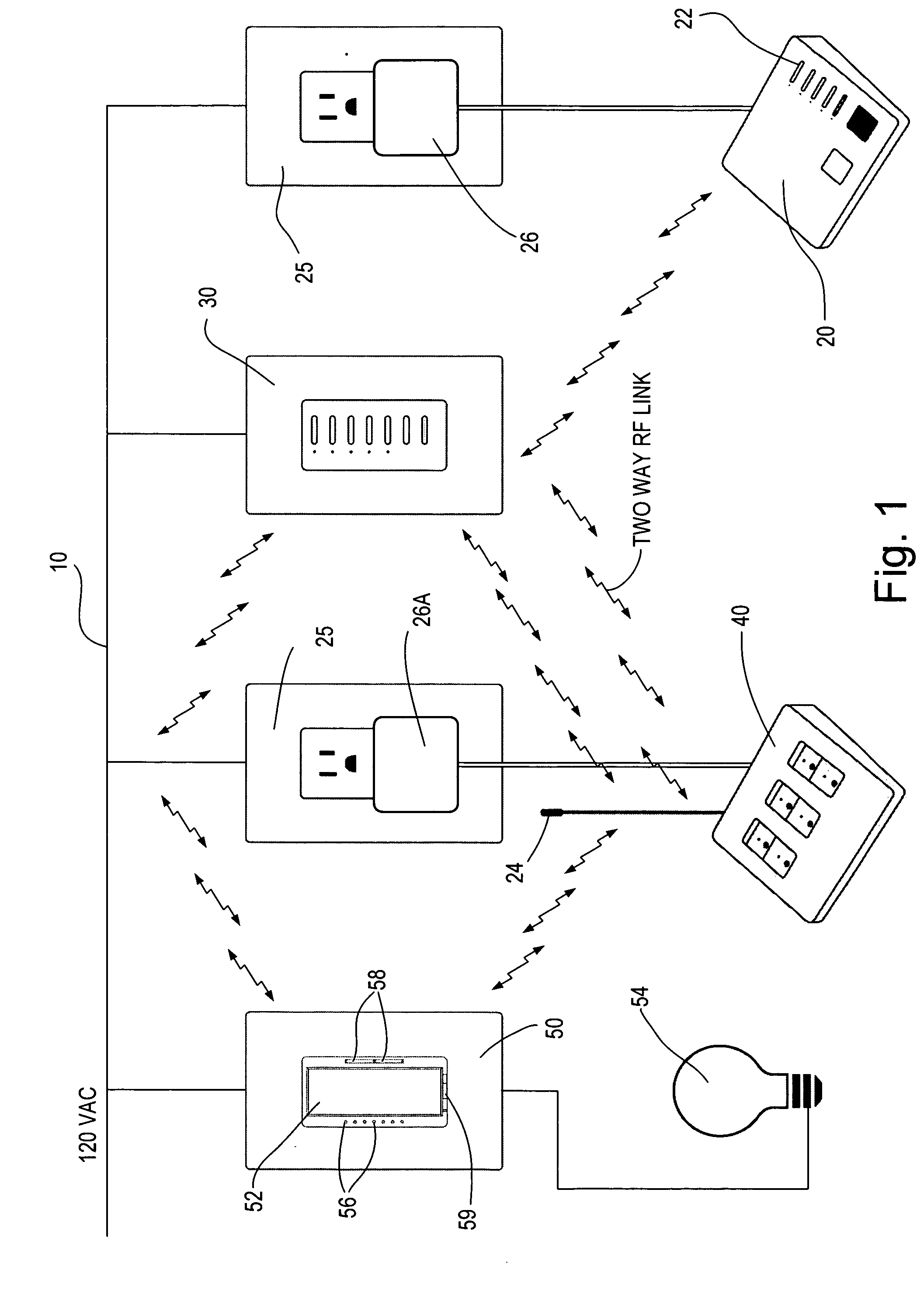
[0046] With reference now to the drawings, the antenna and control unit according to the present invention comprise components of a radio frequency controlled lighting control system. Such a system is connected into the building hardwired electrical power system 10, shown in FIG. 1. Only the hot side of the AC circuit is shown in FIG. 1. The neutral and ground lines are not shown. With the exception of installing lighting control devices to replace the existing standard lighting control switches and dimmers, however, no change in the building wiring is necessary to implement the control functions. Accordingly, the system shown in FIG. 1 can be used to provide remote control of a building lighting system without installing any additional wires. This is particularly useful to retrofit an existing building for remote control without expensive construction work and rewiring. However, systems of this type can also be employed in new construction to reduce the amount of wiring necessary. ...


PUM


Abstract

A compact antenna for use in a device for controlling the power delivered to an electric load and operable to transmit or receive radio frequency signals at a specified frequency is presented. The antenna comprises a first loop of conductive material having a capacitance and an inductance forming a circuit being resonant at the specified frequency, and a second loop of conductive material having two ends adapted to be electrically coupled to an electronic circuit. The second loop is substantially only magnetically coupled to the first loop and is electrically isolated from the first loop. In a first embodiment of the antenna, the first and second loops are formed on respective first and second printed circuit boards, which allow for a small, low-cost antenna that is easy to manufacture and maximizes efficiency. When the antenna is installed in a load control device, such as a dimmer, the first loop of the antenna is mounted on an outer surface of the device. The second loop of the antenna may be at a high-voltage potential such as line voltage.

Description

BACKGROUND OF THE INVENTION [0001] The present invention relates to antennas and in particular, to radio frequency antennas for transmitting and receiving radio frequency (RF) signals. Even more particularly, the present invention relates to a compact antenna, which is provided for use in connection with a radio frequency controlled lighting control system. In particular, the present invention relates to an antenna which is provided on a lighting control device, for example, a light dimmer, and which receives and / or transmits radio frequency signals for controlling a lamp and communicating status of the lamp, for example, on, off, and intensity level. The radio frequency signals are used to control from a remote master location the status of the lamp connected to the light dimmer and also to provide information back to the master location concerning the status of the controlled lamp. The device at the master location may also employ an antenna according to the invention. [0002] The ...

Claims


Application Information

Patent Timeline
Patent Type & Authority Applications(United States)
IPC IPC(8): H01Q1/38H01Q7/00H01Q21/00
CPCH01Q7/005H01Q1/38
Inventor WEBB, SPENCER L.THOMPSON, STEPHEN S.ALTONEN, GREGORY S.DEJONGE, STUARTFELEGY, EDWARD M. JR.SINHA, SIDDHARTH P.
Owner LUTRON TECH CO LLC
Why Eureka
Try Eureka