Automated Dimming Methods and Systems For Lighting

Inactive Publication Date: 2010-07-15
PURESPECTRUM
View PDF21 Cites 165 Cited by
  • Summary
  • Abstract
  • Description
  • Claims
  • Application Information

AI Technical Summary

Benefits of technology

[0020]Dimmable ballast circuits for use with the automated dimming systems of the present application also are disclosed. One such dimmable ballast circuit includes a power source coupled to a first node and a second node, the power source having a current that alternates at a line frequency. The first node and the second node are coupled to each other via a capacitor that stores high frequency energy and provides current at a first (high) frequency, which exceeds the line frequency of the power source and presents a high impedance to the line frequency. A DC voltage varying at twice the line frequency is present across the first terminal and the second terminal of this bypass capacitor, and further the DC voltage drops to 15% or less of a peak value of the DC voltage every half cycle of the line

Problems solved by technology

If not limited, the light source, or the power source, or both, would encounter a catastrophic failure.
Using a conventional dimmer with a conventional ballast operating with a fluorescent light, can lead to problems, because fluorescent lights are not resistive loads, but reactive loads that are primarily capacitive in nature.
Thus, using a convention dimmer on a fluorescent light can lead to flicker or limited operability (dimming) of the light source.
Thus, this can preclude use of a dimmer with a single conventional compact fluorescent light bulb in a lamp.
As a result, conventional dim

Method used


Image

  • Automated Dimming Methods and Systems For Lighting
  • Automated Dimming Methods and Systems For Lighting
  • Automated Dimming Methods and Systems For Lighting

Examples


Embodiment Construction

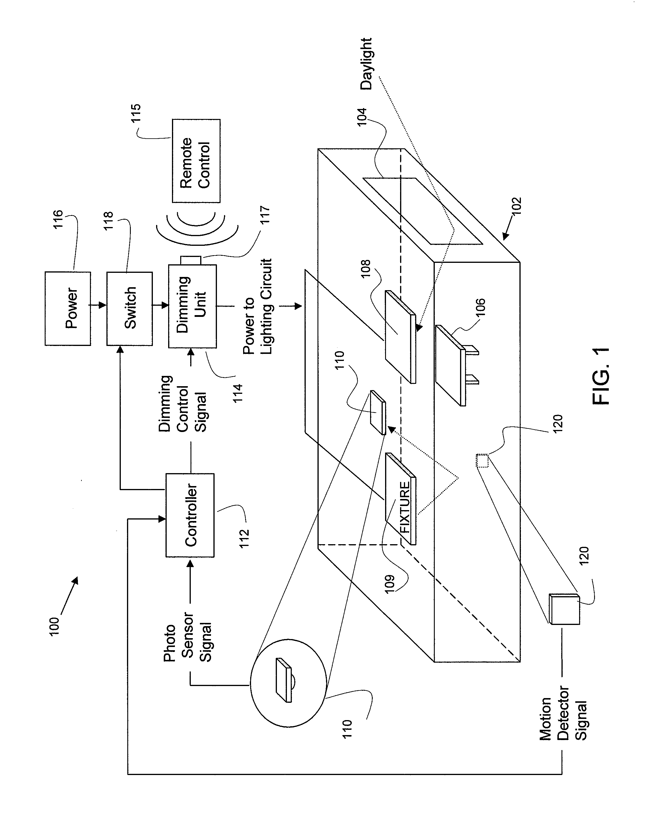
[0046]One application of a daylight harvesting system 100 according to the present invention, in an office environment, is shown diagrammatically and by way of example in FIG. 1. An office 102, shown in isolation from surrounding rooms of a building, includes a window 104, a table 106 providing a work surface, a ceiling fluorescent light fixture 108 between the table and the window, and a second ceiling fluorescent light fixture 109 spaced farther into the room from the window. The daylight harvesting system 100 (described in more detail below) includes a photosensor 110, here shown mounted on the ceiling spaced into the room suitable for closed loop control. In other embodiments, multiple photosensors may be provided. A controller 112 receives a signal from the photosensor or photosensors representing a measurement of the illumination in particular areas of the office from all sources. The photosensor 110, for example, may be positioned to measure illumination from daylight and ele...


PUM


Abstract

Automated control systems and methods for lighting systems are described herein. In certain embodiments, the control systems include either an improved dimmable ballast, an improved dimmer circuit, or both. The control systems are suitable for various applications including a light harvesting system and a security lighting system.

Description

CROSS REFERENCE TO RELATED APPLICATIONS[0001]This application is a continuation-in-part of U.S. application Ser. No. 12 / 397,921, filed Mar. 4, 2009, and a continuation-in-part of U.S. application Ser. No. 12 / 353,551, filed Jan. 14, 2009, both of which are herein incorporated by reference in their entireties.FIELD OF THE INVENTION[0002]The present invention disclosed herein relates generally to energy saving electronic lighting devices and, more particularly, to methods and apparatus for automated dimming of light sources in an efficient and effective manner.BACKGROUND OF THE INVENTION[0003]In the field of electronic lighting ballasts, some light sources (e.g., gas discharge lamps, fluorescent lamps, etc.) generally present a negative resistance, which causes a power source to increase the amount of current provided to the light source. If not limited, the light source, or the power source, or both, would encounter a catastrophic failure. As a result, a ballast circuit is typically p...

Claims


Application Information

Patent Timeline
IPC IPC(8): H05B37/02
CPCH05B37/0245H05B47/175
Inventor KING, RAY JAMES
Owner PURESPECTRUM
Why Eureka
Try Eureka