
Leakage-resistant tissue treatment apparatus and methods of using such tissue treatment apparatus

a tissue treatment and leakage-resistant technology, applied in the field of apparatus and methods for treating tissue with high frequency energy, can solve the problems of heat transfer fluid leakage from the treatment tip before disposal, further tissue contraction, etc., and achieve the effect of reducing the leakage of heat transfer fluid and high frequency energy

Inactive Publication Date: 2012-10-09
THERMAGE INC
View PDF88 Cites 3 Cited by
  • Summary
  • Abstract
  • Description
  • Claims
  • Application Information

AI Technical Summary

Benefits of technology

[0010]In one embodiment, the apparatus includes a treatment tip configured to be removably connected with a handpiece, a conduit inside the handpiece, and a flow control valve inside the handpiece. The treatment tip has an electrode configured to deliver the high frequency energy to a region of the tissue. The conduit includes a tubular sidewall and a lumen bounded by the tubular sidewall. When the treatment tip is coupled with the handpiece, the lumen of the conduit is configured to transfer a heat transfer fluid from the handpiece to a flow passageway in the treatment tip. The flow control valve, which is coupled with the conduit, is configured to occlude the lumen of the conduit, when the treatment tip is removed from the handpiece, for reducing leakage of the heat transfer fluid from the handpiece.

Problems solved by technology

The inflammatory response of the treated tissue causes new collagen to be generated over time (between three days and six months following treatment), which results in further tissue contraction.
Treatment tips are frequently intended for single patient use and, therefore, non-reusable.
The portions of the severed pathways in the handpiece are unblocked, which may permit the heat transfer fluid to leak or drip from the handpiece.
In addition, the portions of the severed pathways in the treatment tip are also unblocked, which may cause heat transfer fluid to leak from the treatment tip before disposal.

Method used


Image

  • Leakage-resistant tissue treatment apparatus and methods of using such tissue treatment apparatus
  • Leakage-resistant tissue treatment apparatus and methods of using such tissue treatment apparatus
  • Leakage-resistant tissue treatment apparatus and methods of using such tissue treatment apparatus

Examples


Embodiment Construction

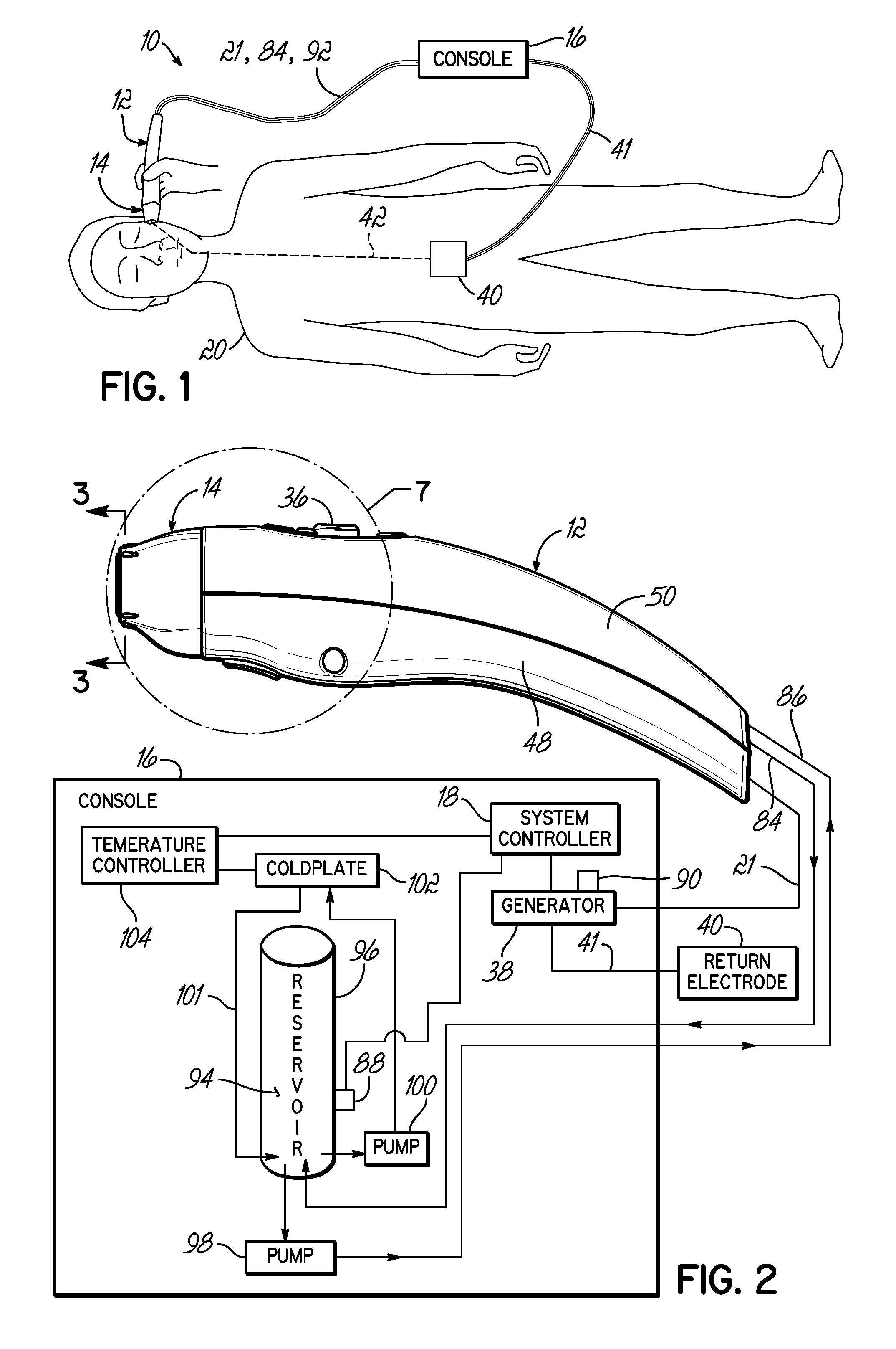
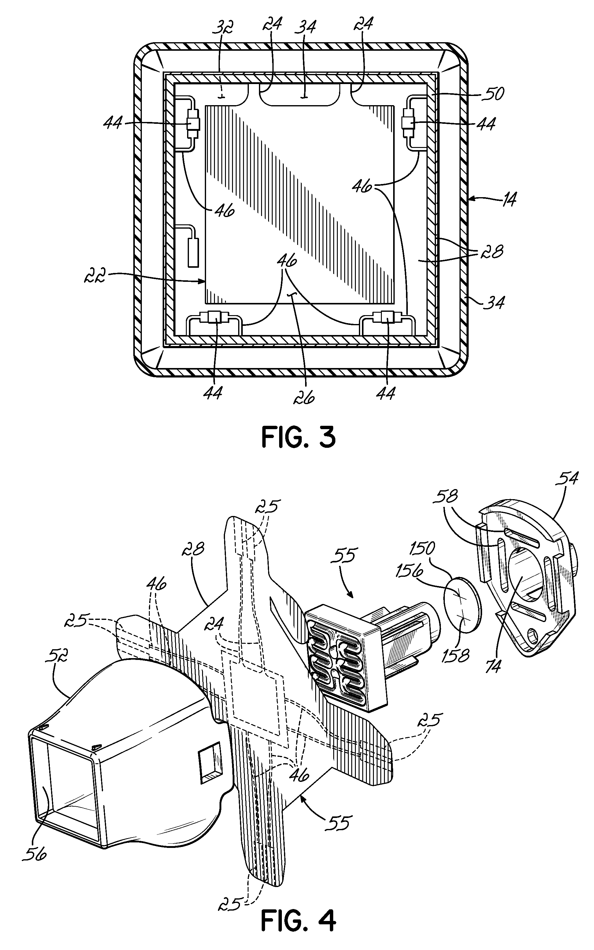
[0022]With reference to FIGS. 1-4, a treatment apparatus 10 includes a handpiece 12, a treatment tip 14 coupled in a removable and releasable manner with the handpiece 12, a console generally indicated by reference numeral 16, and a system controller 18. The system controller 18, which is incorporated into the console 16, controls the global operation of the different individual components of the treatment apparatus 10. Under the control of the system controller 18 and an operator's interaction with the system controller 18 at the console 16, the treatment apparatus 10 is adapted to selectively deliver electromagnetic energy in a high frequency band of the electromagnetic spectrum, such as the radiofrequency (RF) band to non-invasively heat a region of a patient's tissue to a targeted temperature range. The elevation in temperature may produce a desired treatment, such as removing or reducing wrinkles and otherwise tightening the skin to thereby improve the appearance of a patient 2...


PUM


Abstract

Apparatus and methods for treating skin conditions that deliver high frequency energy to a patient's tissue. The apparatus has a treatment tip configured to be removably connected with a handpiece, a conduit inside the handpiece, and a flow control valve inside the handpiece. The treatment tip has an electrode configured to deliver the high frequency energy to a region of the tissue. A lumen of the conduit is configured to transfer a heat transfer fluid from the handpiece to a flow passageway in the treatment tip. When the treatment tip is removed from the handpiece, the flow control valve is configured to occlude the lumen of the conduit for reducing leakage of the heat transfer fluid from the handpiece.

Description

FIELD OF THE INVENTION[0001]The invention generally relates to apparatus and methods for treating tissue with high frequency energy and, more particularly, relates to treatment apparatus and methods for treating tissue with high frequency energy that include liquid-mediated tissue cooling and leakage control mechanisms for the heat transfer fluid used in the liquid-mediated tissue cooling.BACKGROUND OF THE INVENTION[0002]Energy delivery devices that can non-invasively treat tissue are extensively used to therapeutically treat numerous diverse skin conditions. Among other uses, non-invasive energy delivery devices may be used to tighten loose skin to make a patient appear younger, remove skin spots or hair, or kill bacteria. Such non-invasive energy delivery devices emit electromagnetic energy in different regions of the electromagnetic spectrum for tissue treatment.[0003]High frequency treatment devices, such as radio-frequency (RF)-based devices, may be used to treat skin tissue no...

Claims


Application Information

Patent Timeline
Patent Type & Authority Patents(United States)
IPC IPC(8): A61F2/00A61B18/18
CPCA61B18/14A61B2018/00023A61B2018/0091A61B2018/00916
Inventor SCHENCK, ALAN
Owner THERMAGE INC
Learn More