High frequency discharge ignition device

a high-frequency energy conductor and ignition device technology, applied in the direction of spark plugs, machines/engines, mechanical equipment, etc., can solve the problems of difficult to generate spark discharge for initiating combustion, occurrence of a decrease in startability or combustibility, and the difficulty of generating spark discharge, so as to reduce the influence of peripheral devices and shorten the high-frequency energy conductors

Inactive Publication Date: 2018-09-06
MITSUBISHI ELECTRIC CORP
View PDF1 Cites 0 Cited by
  • Summary
  • Abstract
  • Description
  • Claims
  • Application Information

AI Technical Summary

Benefits of technology

[0007]With the high frequency discharge ignition device according to this invention, a high frequency energy supply circuit is directly connected to an output circuit, the output circuit is electrically connected to a spark plug, and the spark plug is grounded, such that the high frequency energy supply circuit is also grounded. Further, the high frequency energy supply circuit is connected to a conducting member which is disposed in a through hole proximate to the output circuit and, as the conducting member is grounded, the high frequency energy supply circuit is also grounded. Accordingly, a loop through which high frequency energy conducts can be shortened.
[0008]As a result, a high frequency discharge ignition device can be provided in which noise generated from a loop through which high frequency energy conducts is suppressed and an influence of this noise on peripheral devices is suppressed.

Problems solved by technology

In recent years, problems relating to environmental conservation and fuel depletion have been raised, and responding to these problems also represents an urgent task in the automobile industry.
However, if a supercharger is used, pressure in an engine combustion chamber becomes extremely high even in a state where combustion is not occurring, making it difficult to generate a spark discharge for initiating combustion.
However, if the spark plug gap is narrowed, loss of thermal energy increases due to the anti-inflammatory effect, that is, the effect by which energy that allows a spark having just been generated to grow is depleted by a low temperature electrode part, which results in the occurrence of a decrease in startability or a decrease in combustibility.

Method used


Image

  • High frequency discharge ignition device
  • High frequency discharge ignition device
  • High frequency discharge ignition device

Examples


first embodiment

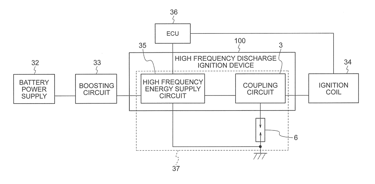
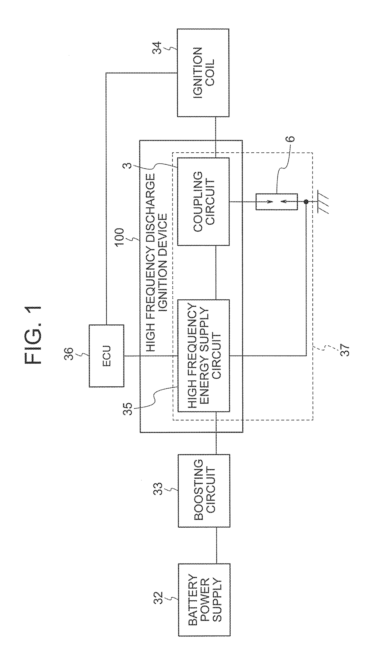
[0018]FIG. 1 is a block diagram showing a circuit configuration of a high frequency discharge ignition device 100 and peripheral devices thereof according to a first embodiment. The high frequency discharge ignition device 100 is constituted by a high frequency energy supply circuit 35 and a coupling circuit 3. The high frequency energy supply circuit 35 generates high frequency energy using the voltage of a battery power supply 32 having been boosted by a boosting circuit 33 as a power supply. The generated high frequency energy and a high voltage pulse supplied from an ignition coil 34 are coupled by the coupling circuit 3 and supplied to a spark plug 6. Drive control of each circuit is performed by an ECU 36. A loop 37 through which high frequency energy conducts is formed by the high frequency energy supply circuit 35, the coupling circuit 3 and the spark plug 6.

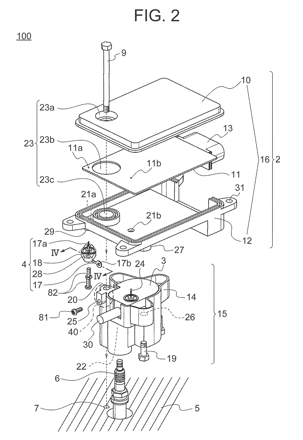
[0019]Components of the high frequency discharge ignition device 100 will be described hereinafter using FIG. 2 to FIG...

second embodiment

[0055]Next, a high frequency discharge ignition device 110 according to a second embodiment will be described using FIG. 6. The shape of a connecting member of a terminal ASSY 4 is different from that of the first embodiment.

[0056]FIG. 6 is a broken-down perspective view showing an internal structure of the high frequency discharge ignition device 110. As shown in FIG. 6, a connecting member 170 of the terminal ASSY 4 is U-shaped and has, at one end thereof, a second connecting portion 17c which is provided with a screw terminal having a hole that passes therethrough in the vertical direction. The second connecting portion 17c is electrically connected to the bolt 9 by being sandwiched between the bolt 9 and the first housing 14.

[0057]As indicated above, in the high frequency discharge ignition device 110 according to the second embodiment, the connecting member 170 is electrically connected to the bolt 9 by being sandwiched between the bolt 9 and the first housing 14.

[0058]As a res...

third embodiment

[0060]Next, a high frequency discharge ignition device 111 according to a third embodiment will be described using FIG. 7. In the first embodiment, the conducting member is a hexagonal bolt, however, in the third embodiment, the shape of the bolt differs from that in the first embodiment and is a hexagonal socket head bolt.

[0061]When the conducting member is a hexagonal bolt, as in the first embodiment, the diameter of a socket wrench for tightening the bolt 9 is larger than the diameter of the head of the bolt 9. Therefore, when also taking into account an operating range of the socket wrench, the diameter of the space 23 in the second housing 16 through which the socket wrench is inserted must be sufficiently larger than the diameter of the bolt 9.

[0062]On the other hand, when the conducting member is a hexagonal socket head bolt 90 as in the third embodiment, the diameter of a hexagonal wrench for tightening the hexagonal socket head bolt 90 is smaller than the diameter of the of...


PUM


Abstract

A problem exists in that, as a loop through which high frequency energy conducts is long, it is difficult to suppress noise generated from the loop and suppress an influence thereof on peripheral equipment. A high frequency discharge ignition device according to this invention is a structure integrally constituted by a second housing into which a high frequency energy supply circuit is built and a first housing into which an output circuit is built, wherein the high frequency energy supply circuit is connected to the output circuit by a connection terminal so as to be connected to a spark plug which is mounted on a grounded object. Further, the high frequency energy supply circuit is grounded via a conducting member disposed in a through hole provided in the first housing.

Description

BACKGROUND OF THE INVENTION1. Field of the Invention[0001]This invention relates to a high frequency discharge ignition device to be used mainly in an internal combustion engine.2. Description of the Related Art[0002]In recent years, problems relating to environmental conservation and fuel depletion have been raised, and responding to these problems also represents an urgent task in the automobile industry. As an example of a response thereto, there exists a method in which fuel consumption is improved through engine downsizing using a supercharger. However, if a supercharger is used, pressure in an engine combustion chamber becomes extremely high even in a state where combustion is not occurring, making it difficult to generate a spark discharge for initiating combustion. For this reason, a spark plug gap is narrowed. However, if the spark plug gap is narrowed, loss of thermal energy increases due to the anti-inflammatory effect, that is, the effect by which energy that allows a sp...

Claims


Application Information

Patent Timeline
Patent Type & Authority Applications(United States)
IPC IPC(8): H01T13/05H01T13/06
CPCH01T13/05H01T13/06F02P3/01F02P3/02F02P9/007F02P13/00F02P15/00H01T13/40
Inventor TANAKA, TAKAAKISHIMIZU, YASUYUKI
Owner MITSUBISHI ELECTRIC CORP
Why Eureka
Try Eureka