Automatic lengthening bone fixation device

a technology of bone fixation device and automatic lengthening, which is applied in the field of orthopedic spine surgery, can solve the problems of requiring surgery, requiring a surgical procedure, and requiring an additional level of complexity of the type of system, and achieves the effect of less desirable spinal fusion, reducing the complexity of the system, and improving the quality of li

Inactive Publication Date: 2009-08-13
K2M
View PDF48 Cites 113 Cited by
  • Summary
  • Abstract
  • Description
  • Claims
  • Application Information

AI Technical Summary

Problems solved by technology

In younger patients, performing a spinal fusion is less desirable since it will interfere with the normal growth of an individual.
A major disadvantage of the currently available growing rod systems is that they require a surgical procedure for manually increasing the length of the rod, usually by loosening one or more set screws, providing distraction between two rod segments, and then re-tightening.
This type of system requires an additional level of complexity using active elements and possibly some type of power source.
The currently available devices do not passively allow growing rods to lengthen as the spine grows while maintaining structure and stability.

Method used


Image

  • Automatic lengthening bone fixation device
  • Automatic lengthening bone fixation device
  • Automatic lengthening bone fixation device

Examples


Embodiment Construction

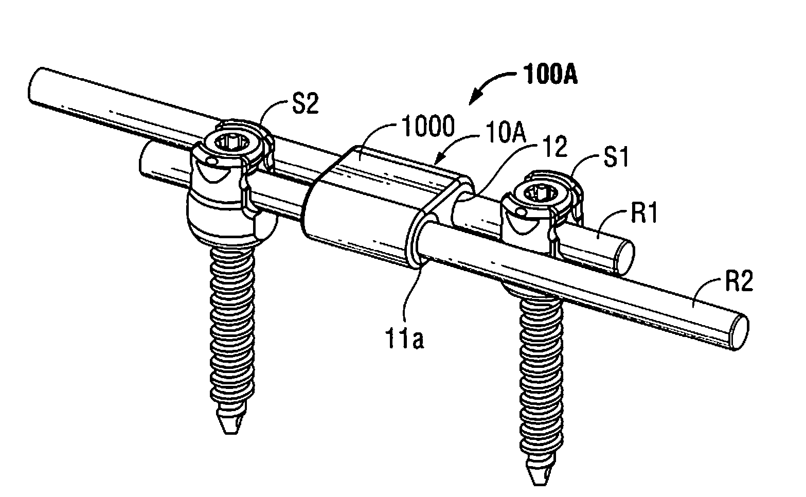
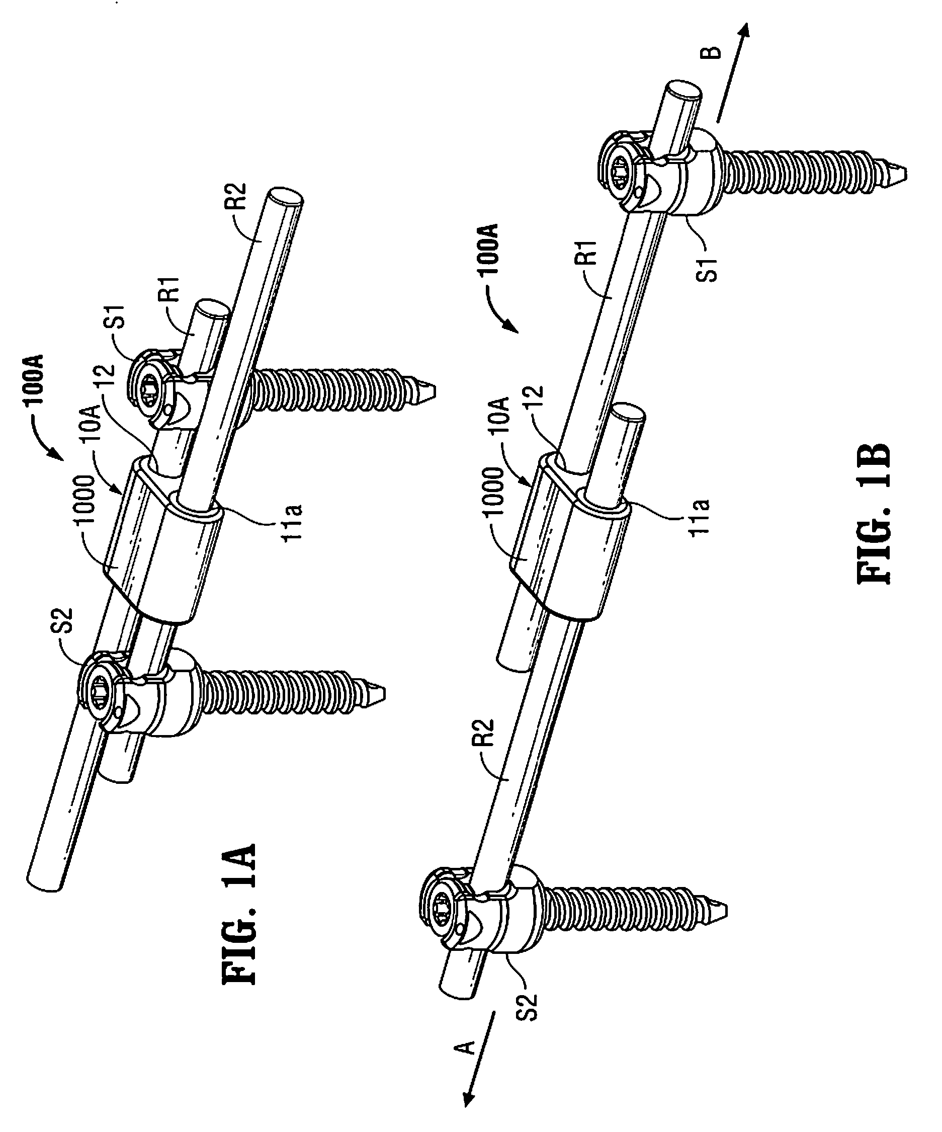
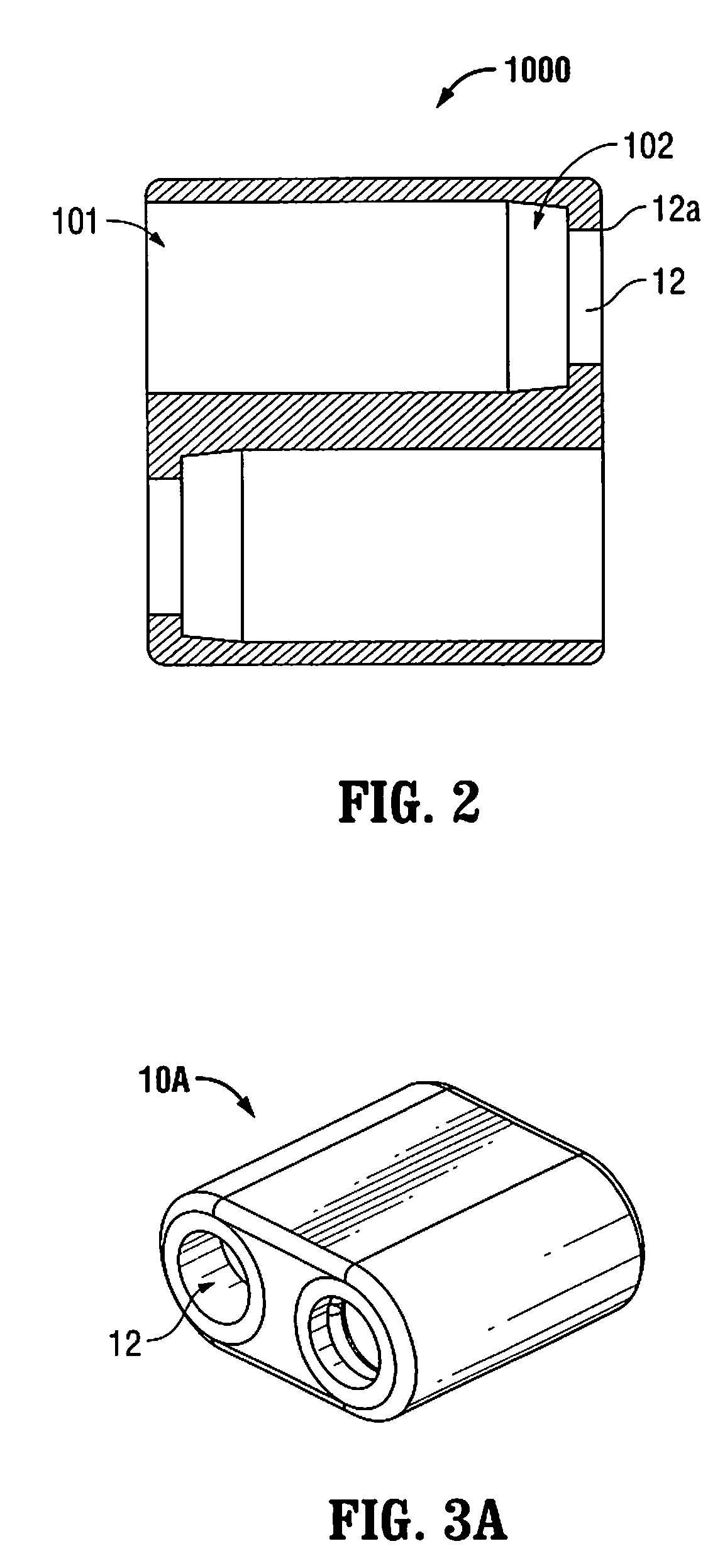
[0049]Particular embodiments of the present disclosure will be described herein with reference to the accompanying drawings. In the following description, well-known functions or constructions are not described in detail to avoid obscuring the present disclosure in unnecessary detail. As shown in the drawings and as described throughout the following descriptions, and as is traditional when referring to relative positioning on an object, the term “proximal,” will refer to the end of a device or system that is closest to the operator, while the term “distal” will refer to the end of the device or system that is farthest from the operator. In addition, the term “cephalad” is used in this application to indicate a direction toward a patient's head, whereas the term “caudad” indicates a direction toward the patient's feet. Further still, for purposes of this application, the term “medial” indicates a direction toward a side of the body of the patient, i.e., away from the middle of the b...


PUM


Abstract

A bone fixation device adapted to be coupled to bone anchors that allows movement of rods to permit a screw-rod construct to lengthen in response to bone growth without necessitating post surgical installation adjustment of the device. The bone fixation device includes a locking mechanism that is operably associated with a housing to allow relative movement of a rod and a housing in a first direction and inhibiting relative movement of the rod and the housing in a second direction.

Description

CROSS-REFERENCE TO RELATED APPLICATIONS[0001]This application claims priority to, and the benefit of, U.S. Provisional Application Ser. No. 61 / 063,942, filed on Feb. 7, 2008, U.S. Provisional Application Ser. No. 61 / 063,943, filed on Feb. 7, 2008, and U.S. Provisional Ser. No. 61 / 188,089, filed on Aug. 6, 2008. The disclosures of each of these prior applications are incorporated herein by reference in their entirety.BACKGROUND[0002]1. Technical Field[0003]The present disclosure relates to a device for use in orthopedic spine surgery. In particular, the present disclosure relates to a device for fixating a bone that is able to lengthen in response to bone growth.[0004]2. Background of Related Art[0005]The human spine is comprised of thirty-three vertebrae at birth and twenty-four as a mature adult. The vertebra includes the vertebral body and posterior elements, including the spinous process, transverse processes, facet joints, laminae, and pedicles. The vertebral body consists of a ...

Claims


Application Information

Patent Timeline
Patent Type & Authority Applications(United States)
IPC IPC(8): A61B17/70
CPCA61B17/7002A61B17/7014A61B17/705A61B17/7041A61B17/7032A61B2090/034
Inventor MCCLINTOCK, LARRYSTRAUSS, KEVIN R.DURRANI, ATIQAKBARNIA, BEHROOZ
Owner K2M
Why Eureka
Try Eureka