Indoor location determination system and method

a technology for location determination and indoors, applied in wave based measurement systems, instruments, reradiation, etc., can solve the problems of increased measurement error, serious influence of channel conditions on distance estimation using ssr, and increased measurement error under nlos(non-line of sight) channel conditions

Inactive Publication Date: 2009-08-13
SAMSUNG ELECTRONICS CO LTD
View PDF4 Cites 5 Cited by
  • Summary
  • Abstract
  • Description
  • Claims
  • Application Information

AI Technical Summary

Problems solved by technology

The distance estimation using SSR is, however, seriously affected by channel conditions.
Particularly, an error in measurement is increased due to NLOS (non-line of sight) channel conditions or multipath fading.
However, an error in measurement is increased under NLOS(Non-Line Of Sight) channel conditions.
These methods, such as TOA or TDOA, for ascertaining the location of each node by using a time or time difference have difficulty in calculating an exact time difference under the influence of environmental conditions.
Accordingly, a receiver node receives overlapped signals through the multiple paths and thereby may often fail to measure exactly the arrival time of a real transmission signal.

Method used


Image

  • Indoor location determination system and method
  • Indoor location determination system and method
  • Indoor location determination system and method

Examples


Embodiment Construction

[0018]Exemplary, non-limiting embodiments of the present invention are described more fully herein, with reference to the accompanying drawings. This invention may, however, be embodied in many different forms and should not be construed as limited to the exemplary embodiments set forth herein. Rather, the disclosed embodiments are provided so that this disclosure will be thorough and complete, and will fully convey the scope of the invention to those skilled in the art. The principles and features of this invention may be employed in varied and numerous embodiments without departing from the scope of the invention.

[0019]Well-known configurations and processes may be not described or illustrated in detail to avoid obscuring the essence of the present invention.

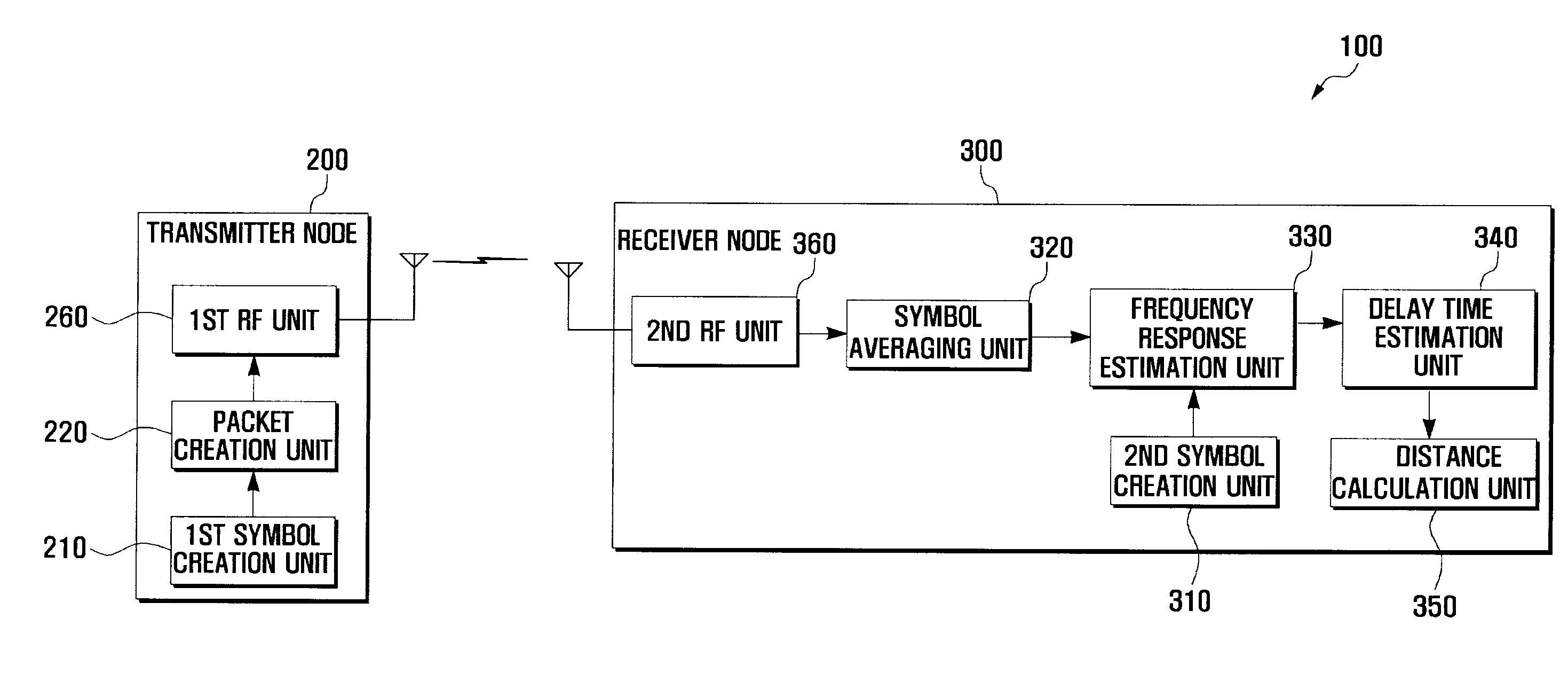
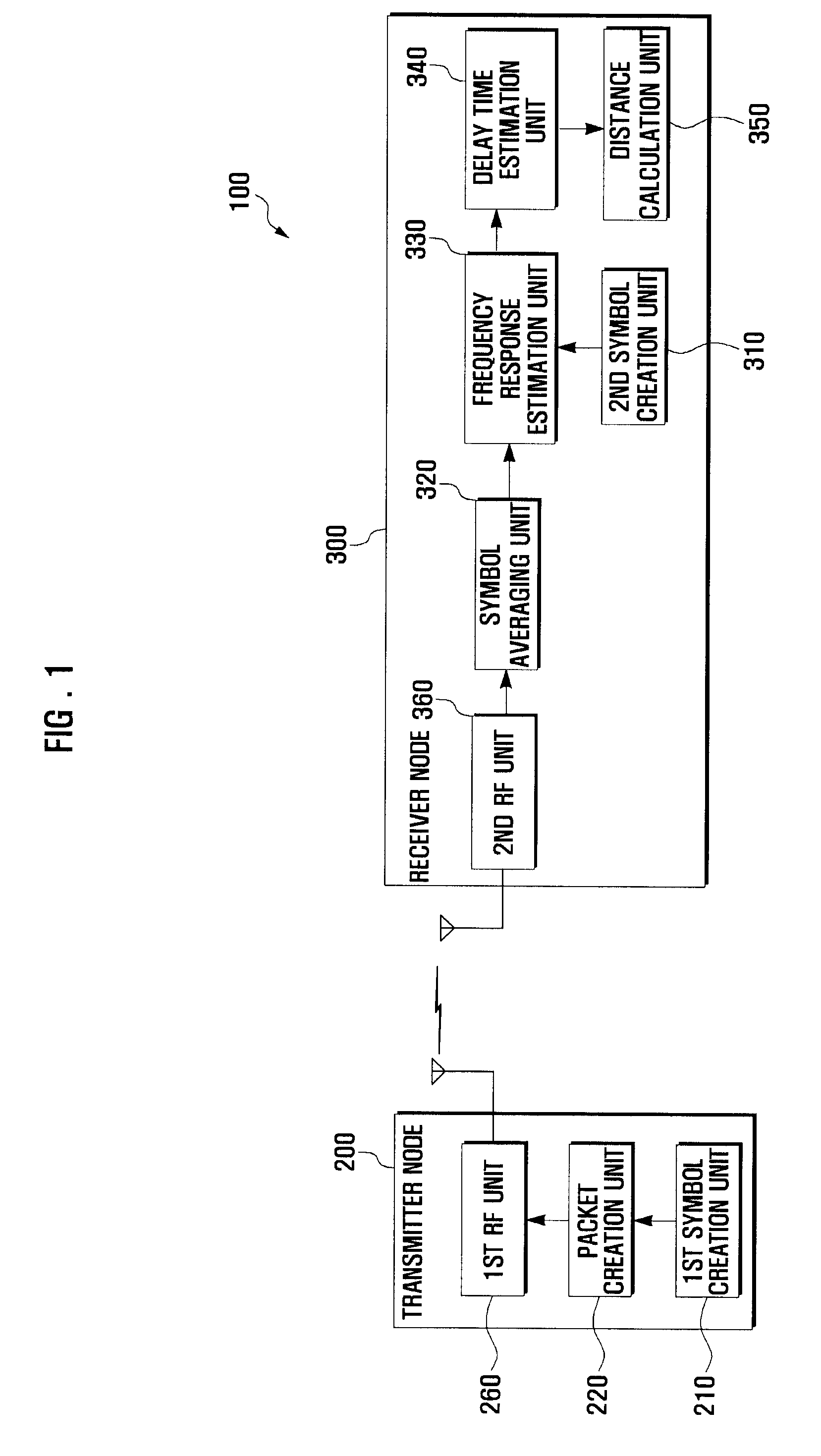
[0020]FIG. 1 is a block diagram showing an indoor location determination system in accordance with an exemplary embodiment of the present invention.

[0021]Referring to FIG. 1, the system 100 for indoor location determination in...


PUM


Abstract

Disclosed are a system and a method for an indoor location determination using a matrix pencil. The system comprises a transmitter node that creates and transmits a transmission packet having a plurality of same symbols. A receiver node receives the transmission packet, calculates a delay time by using the symbols in the transmission packet and a matrix pencil algorithm, and calculates a distance between the transmitter node and the receiver node by using the delay time. The delay time estimation using the matrix pencil can reduce an error ratio and therefore can estimate more exactly the distance between the nodes.

Description

CLAIM OF PRIORITY[0001]This application claims the benefit of the earlier filing date, pursuant to 35 USC 119, to that patent application entitled “INDOOR LOCATION DETERMINATION SYSTEM AND METHOD” filed in the Korean Intellectual Property Office on Feb. 13, 2008 and assigned Serial No. 10-2008-0012869, the contents of which are incorporated herein by reference.BACKGROUND OF THE INVENTION[0002]1. Field of the Invention[0003]The present invention relates to location technology and, more particularly, to an indoor location determination system and a method thereof, which may allow a more exact measurement of the distance between two points by using a matrix pencil.[0004]2. Description of the Related Art[0005]Indoor location determination technology is a method for measuring the motion of an object in a room or a building. As one of such technologies, a technique for determining the distance between two points, (hereinafter, referred to as nodes) by using radio-frequency waves such as u...

Claims


Application Information

Patent Timeline
Patent Type & Authority Applications(United States)
IPC IPC(8): G06F15/00G01S5/02G01S11/02
CPCG01S5/0221G01S11/06G01S11/02G01S2205/02
Inventor PARK, SUNG KWEONKIM, JOON OOOH, YUN JEKANG, JOON HYUKKIM, NA YOUNGLEE, JEONG SUKIM, SU JINKIM, JAE HWAN
Owner SAMSUNG ELECTRONICS CO LTD
Why Eureka
Try Eureka