Residential fireplace insert system improvements

a technology for insert systems and fireplaces, applied in the field of improvements to the system of residence fireplace inserts, can solve the problems of drying out carbon dust particles up the chimney, all models “leak” air volumes into the combustion chamber without real heat or fuel consumption control, and achieve the effect of sufficient room heating and suitable consistant oxygen burning ratio for consuming fuel

Inactive Publication Date: 2009-08-20
SCHREFFLER ROBERT ZERBY
View PDF4 Cites 1 Cited by
  • Summary
  • Abstract
  • Description
  • Claims
  • Application Information

AI Technical Summary

Problems solved by technology

During the nearly three-year period of time the parent application was going through the examination period, testing and evaluations were constant challenges to obtain the optimum target conditions for fireplace efficiency.
Early on, it became evident that the “standard” door closures of the industry were woefully inefficient.
All models “leaked” air volumes into the combustion chamber with no real heat or fuel consumption controls.
Therefore, the longer the churning of heated air, the better is the chance the moisture can be driven off and the dried-out carbon dust particle component might be exhausted up the chimney.
If this occurs and the water evaporation takes place, the result is a “baked-on” soot deposit which is quite difficult to remove.

Method used


Image

  • Residential fireplace insert system improvements
  • Residential fireplace insert system improvements

Examples


Embodiment Construction

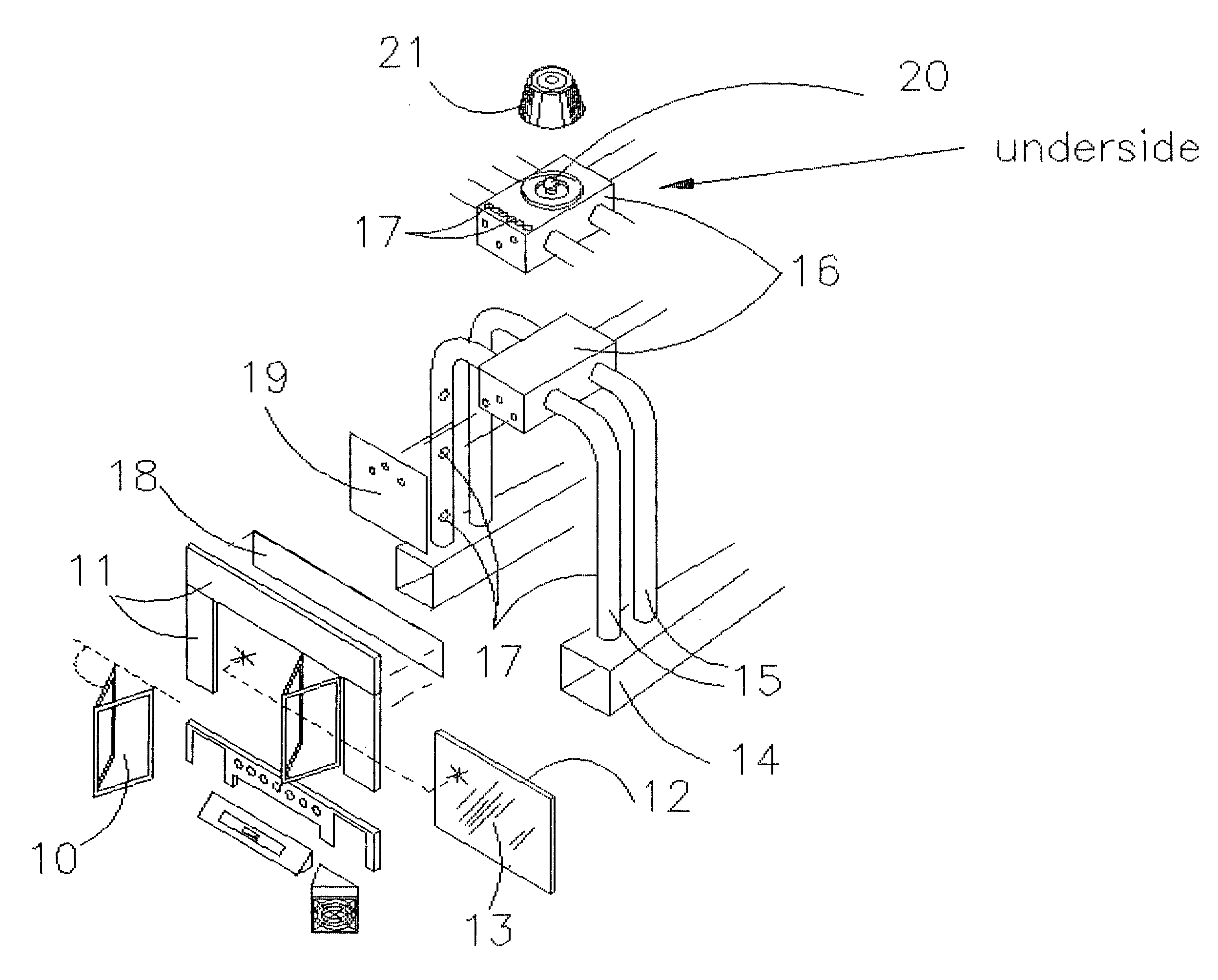
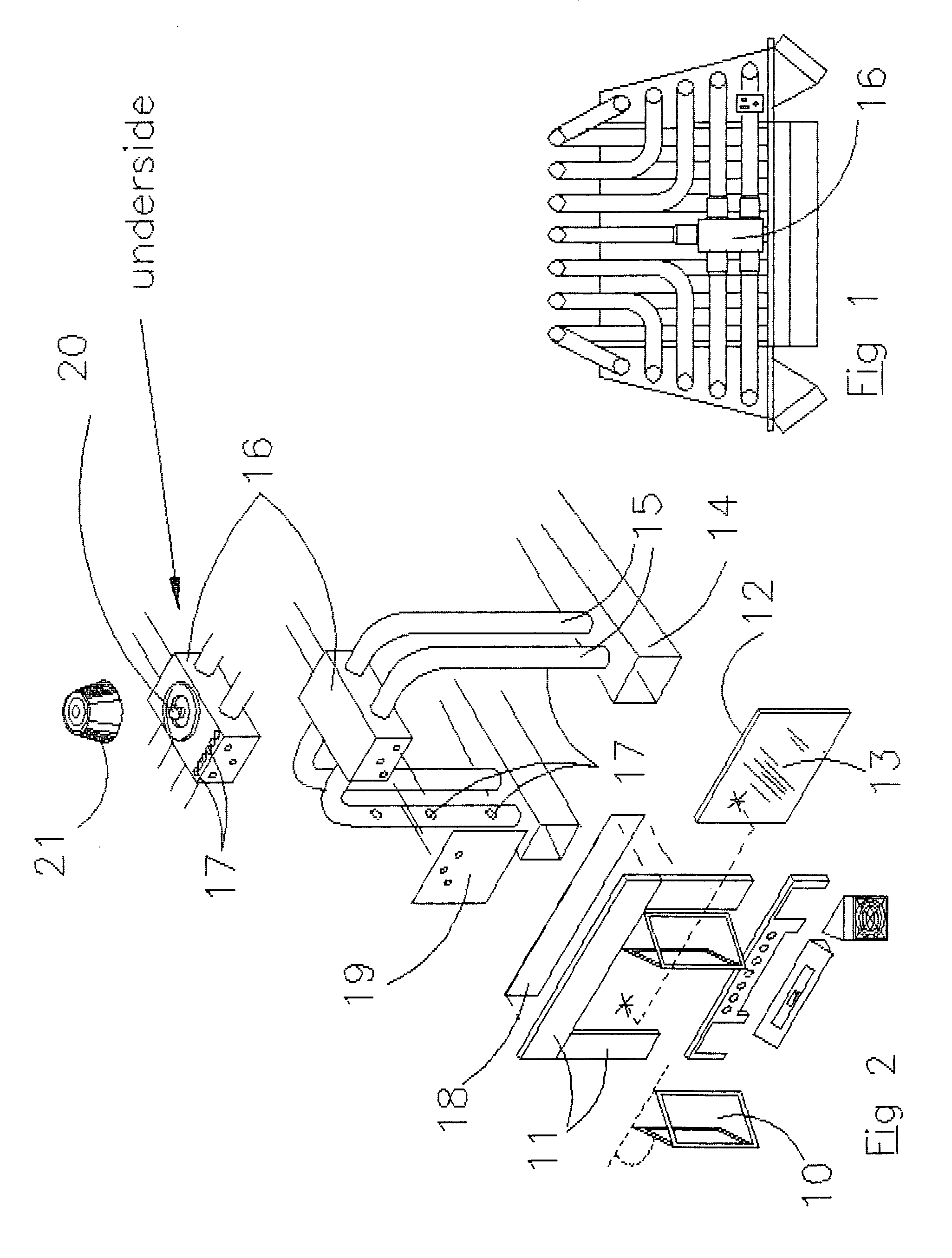
[0010]FIG. 1 is a plan top view identifying manifold 16.

[0011]FIG. 2 is an exploded front quarter-view of the fireplace insert FIG. 1. The hinged door closures 10 are mounted onto the surround 11 in a customary way and can be completely opened wide as indicated. A thin rigid metal frame 12, on which a temperature-tolerant plastic film 13, is stretched and mounted has nearly the same overall dimensions as the said hinged door closures 10 and is able to be stored behind the closed said door closures 10. Attached to the back side of the said surround 11 is a soot deflector 18, a narrow, thin-gage panel of metal

attached to shield the top three or four inches of the said surround 11 opening from soot accumulation. The said soot deflector 18 and deflector 19 help generate a “swirling” air purging action with assistance from a plurality of small openings called air purges 17. These said air purge holes 17 are especially located in the tubular means 15 which contain moving columns of air un...


PUM


Abstract

This CIP titled “Residential Fireplace Insert System Improvements” involves an improvement in the efficiency of the slide-in “Residential Woodburning Fireplace Insert System”, formerly application Ser. No. 11 / 507,343 filed Aug. 21, 2006, (now Pat. No. 7,509,954) wherein the heat output and fuel consumption are improved by controllably shutting off free air flow into the the combustion chamber by using a framed panel of heat-tolerant plastic film (as an alternate to using the glass doors) at the surround door location, then controlling the generated heat and fuel combination by carefully injecting just the proper ratio of the oxygen-to-fuel necessary for controlling both the heat output rate and fuel consumption parameters which include soot and creosote control improvements.

Description

CROSS REFERENCE This Sub-Spec Contains No New Matter[0001]This application is a Continuation-In-Part to: “Residential Fireplace Insert System”, (Pat. No. 7,509,954).FIELD OF THE INVENTION[0002]These improvements relate to the normal advancements, innovations and improvements discovered during the almost three-year period the parent application was wending its way through the examination process. In few words these discoveries center around a modification to the bifold glass door closure area, supplementary air controls within the heat combustion area, modification for soot and creosote control and a dome light mounted to the under-underside of the tubing air manifold for close observation of needed fine adjustments.BACKGROUND OF THE INVENTION[0003]The “Continuation-In-Part” will be described with reference to the Parent application Ser. No. 11 / 507,343 filed Jun. 6, 2008, but persons skilled in the art will recognize the continuation in part where improvement in the art is effected.P...

Claims


Application Information

Patent Timeline
Patent Type & Authority Applications(United States)
IPC IPC(8): F24B1/189F24B13/00
CPCF24B1/1888
Inventor SCHREFFLER, ROBERT ZERBY
Owner SCHREFFLER ROBERT ZERBY
Why Eureka
Try Eureka