Method and apparatus for delivering two fuels to a direct injection internal combustion engine

a technology of internal combustion engine and fuel delivery method, which is applied in the direction of engine components, mechanical equipment, machines/engines, etc., can solve the problems of increasing the capital cost of the engine and/or the operating cost, and increasing the cost of the engine. , to achieve the effect of saving the operating cost of the engine and being less expensiv

Active Publication Date: 2008-05-20
WESTPORT FUEL SYST CANADA INC
View PDF7 Cites 125 Cited by
  • Summary
  • Abstract
  • Description
  • Claims
  • Application Information

AI Technical Summary

Benefits of technology

[0010]An advantage of storing a gaseous fuel in liquefied form at a cryogenic temperature is that a much higher energy density can be achieved compared to the same gaseous fuel stored at high pressure in the gaseous phase. However, if the gaseous-fuel supply system is for a vehicle with only short range routes and / or where high-pressure gaseous fuel is readily available for re-fueling, it is possible to use a gaseous-fuel storage vessel that is a pressure vessel in which the gaseous fuel can be stored under pressure and in such embodiments the gaseous-fuel pressurizing device can be a compressor. In some markets this can be a preferred approach if there is greater familiarity with handling high pressure gases, versus cryogenic fluids, and where there is an established re-filling network for gaseous fuels. When a compressor is employed to pressurize the gaseous fuel the gaseous-fuel supply system can further comprise a heat exchanger disposed between the compressor and the gaseous-fuel rail for cooling the gaseous fuel after it is discharged from the compressor.
[0012]In addition to a portion of the liquid-fuel rail being disposed within the cylinder head, similar advantages can be realized if a portion of the gaseous-fuel rail and / or the drain rail comprises a bore disposed with the cylinder head. That is, in a preferred embodiment, portions of each one of the liquid-fuel rail, the gaseous-fuel rail, and the drain rail all comprise respective bores disposed within the cylinder head.
[0020]In preferred methods pressure within the liquid-fuel storage vessel is maintained at or near atmospheric pressure by connecting the vent pipe to the liquid-fuel storage vessel. The method can further comprise preventing liquid fuel from escaping through the vent line by blocking fluid flow through the vent pipe if the liquid-fuel storage vessel tips onto its side or up-side-down.
[0025]There can also be economic advantages associated with substituting a gaseous fuel for diesel fuel, since in many markets around the world, gaseous fuels are less expensive than diesel fuel on an energy basis, and if the gaseous fuels can be consumed in an engine with the same efficiencies as diesel fuels, this can result in a significant savings in the operating costs for the engine. In addition, geographically, compared to oil, natural gas as a resource is more broadly available, with many more countries having larger natural gas reserves than oil reserves, providing a potentially more secure supply of fuel.

Problems solved by technology

However, a disadvantage of diesel engines is that they can produce more pollution, such as particulate matter (soot) and NOx, which are subject to increasingly stringent regulations that require such emissions to be progressively reduced over time.
However, most of these approaches add to the capital cost of the engine and / or the operating costs.
However, with this approach, engines have been unable to match the performance and efficiency of diesel engines.
A problem with delivering two different fuels for injection directly into the combustion chambers of an internal combustion engine, is that it can be difficult to find the physical space for two fuel injection valves per cylinder and space near the fuel injection valves to provide two high pressure fuel rails in addition to drain lines for taking away fuel that may leak from the fuel injection valves and fluid that is drained from control chambers of hydraulically actuated fuel injection valves.

Method used


Image

  • Method and apparatus for delivering two fuels to a direct injection internal combustion engine
  • Method and apparatus for delivering two fuels to a direct injection internal combustion engine
  • Method and apparatus for delivering two fuels to a direct injection internal combustion engine

Examples


Embodiment Construction

)

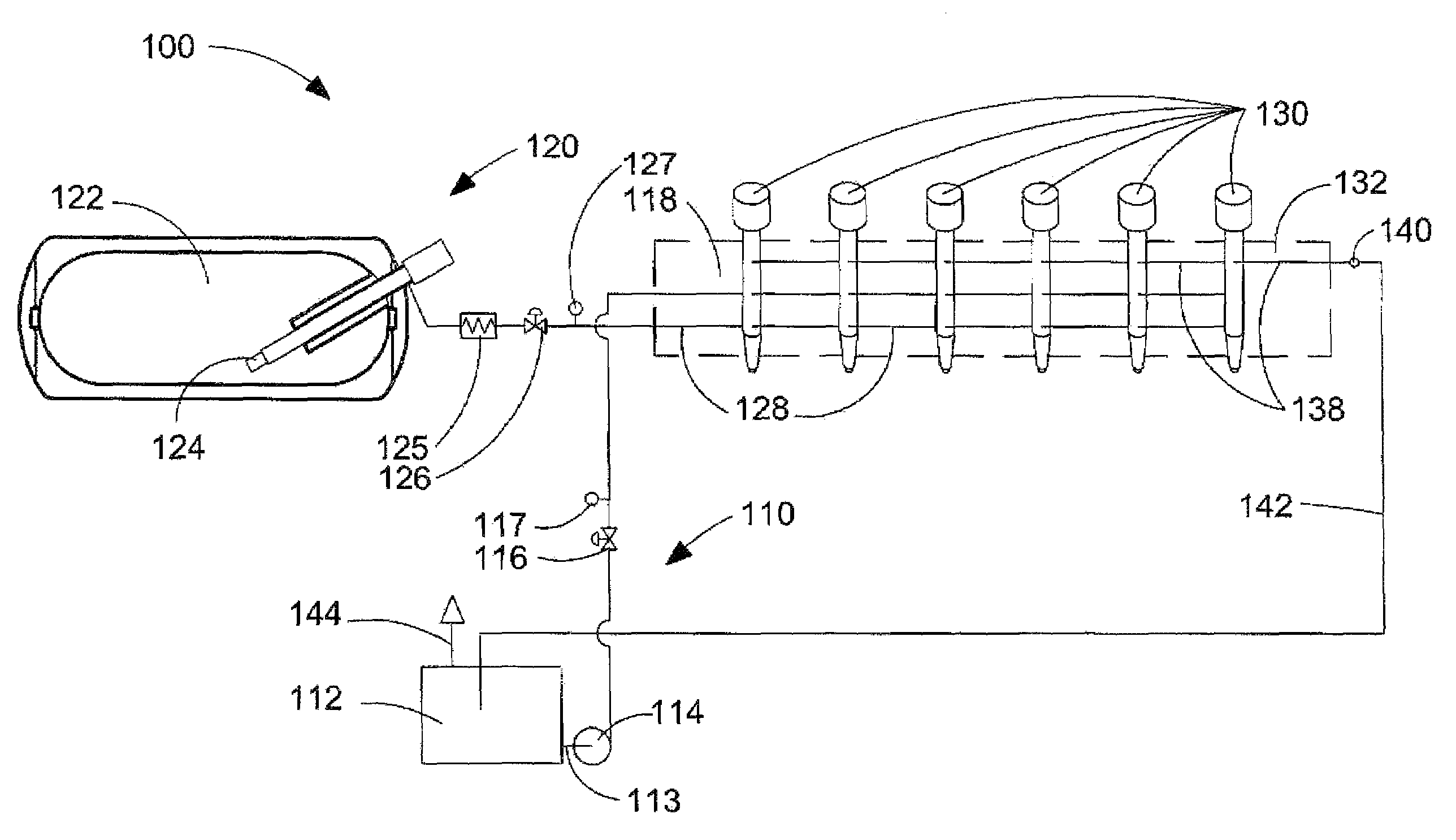
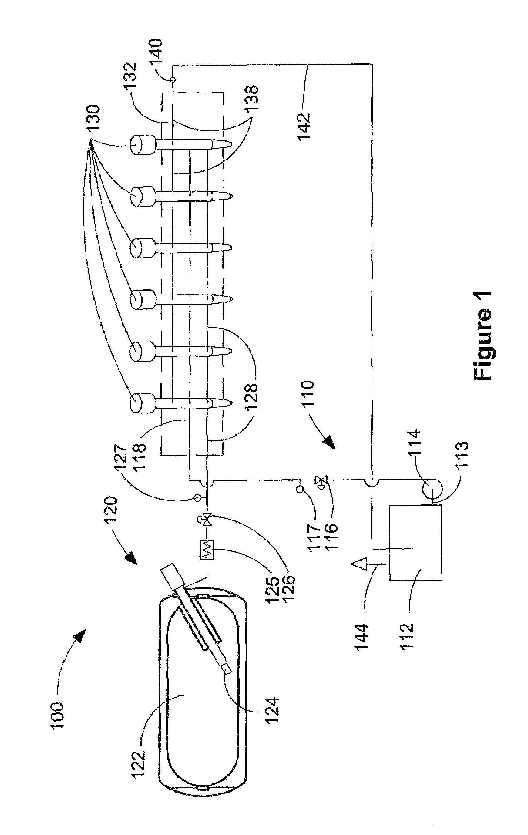
[0029]FIG. 1 is a schematic view of apparatus 100, which delivers a liquid fuel and a gaseous fuel into a combustion chamber of an internal combustion engine. Apparatus 100 comprises liquid-fuel supply system 110, which itself comprises liquid-fuel storage vessel 112, suction line 113, liquid-fuel pump 114, pressure control valve 116, optional pressure sensor 117, and liquid-fuel rail 118. Apparatus 100 further comprises gaseous-fuel supply system 120, which itself comprises gaseous-fuel storage vessel 122, gaseous-fuel pump 124, heat exchanger 125, pressure control valve 126, optional pressure sensor 127, and gaseous-fuel rail 128. Optional pressure sensors 117 and 127 can be employed to respectively monitor liquid and gaseous fuel pressure to ensure that liquid-fuel supply system 110 and gaseous-fuel supply system 120 are functioning normally.

[0030]The engine comprises a plurality of fuel injection valves 130, which are mounted in cylinder head 132. In FIG. 1, cylinder head 132 i...


PUM


Abstract

An apparatus for delivering two fuels to a direct injection internal combustion engine comprises a liquid-fuel supply rail, a gaseous-fuel supply rail, a drain system with a shared drain rail for collecting both liquid fuel and gaseous fuel, and a venting device for venting gaseous fuel collected by the drain rail. The method comprises separately delivering a liquid fuel at injection pressure to an injection valve through a liquid-fuel rail, and actuating the liquid-fuel injection valve to introduce liquid fuel directly into the combustion chamber. The method further comprises delivering a gaseous fuel at injection pressure to an injection valve through a gaseous-fuel rail and actuating the gaseous-fuel injection valve to introduce gaseous fuel directly into the combustion chamber. The method further comprises collecting in a drain rail liquid fuel and gaseous fuel from the liquid-fuel injection valve and the gaseous-fuel injection valve, directing liquid fuel to a storage vessel, and directing gaseous fuel to a vent pipe.

Description

FIELD OF THE INVENTION[0001]The present invention relates to a method and apparatus for delivering two fuels to a direct injection internal combustion engine. More specifically, the invention relates to a fuel system that keeps the two fuels separate until they are separately and independently introduced directly into the engine's combustion chamber and a drain system for draining both fuels from the fuel system.BACKGROUND OF THE INVENTION[0002]Engines that burn diesel fuel are the most popular type of compression ignition engines. So-called diesel engines introduce fuel at high pressure directly into the combustion chamber. Diesel engines are very efficient because this allows high compression ratios to be employed without the danger of knocking, which is the premature detonation of the fuel mixture inside the combustion chamber. Because diesel engines introduce their fuel directly into the combustion chamber, the fuel injection pressure must be greater than the pressure inside the...

Claims


Application Information

Patent Timeline
Patent Type & Authority Patents(United States)
IPC IPC(8): F02M21/02F02B3/00
CPCF02D19/0605F02D19/0628F02D19/0684F02D19/105F02M21/0287F02M43/00F02M43/04F02M47/027F02M55/002F02M55/007F02M61/182F02M63/0225F02M63/029F02D19/0694F02B2275/14F02M63/004F02M63/0043F02M2200/16F02M2200/46F02M2200/9007F02M2200/9053F02M2547/006Y02T10/36Y02T10/123Y02T10/32F02D19/0647Y02T10/12Y02T10/30
Inventor LENNOX, TIMPOST, ADRIANWICKSTONE, MICHAEL
Owner WESTPORT FUEL SYST CANADA INC
Why Eureka
Try Eureka