Multi-Microprocessor System and Control Method for the Same
Active Publication Date: 2009-08-20
XUESHAN TECH INC
7 Cites 4 Cited by
AI-Extracted Technical Summary
Problems solved by technology
However, such reset or restart method results in loss of p...
Method used
[0019]The foregoing setting values include user-defined setting values, for instance. By duplicating the setting values to the storage device 106 and loading the setting values back into the first microprocessor 102, the first microprocessor 102 having been restarted or reset is stored with the same setting values as before being restarted or reset. Thus, after the first microprocessor 102 is restarted or reset, the entire system is restored to user-defined conditions as before the first microprocessor 102 crashed, such that the user does not even experience the crash but smoothly continue in using the system. Further, the setting values may also include variable values of programs executed by the first microprocessor 102 before the first microprocessor 102 crashed. Hence, loaded variable values facilitate the first microprocessor 102 to instantaneously resume an operating state before the crash to complete any unfinished tasks.
[0022]In this embodiment, suppose a micro code of the first microprocessor 102 is stored in the storage device 106 or another storage device (not shown), e.g. a flash memory. The micro code is a code to be executed by the first microprocessor 102 under normal operating conditions. When the second microprocessor 104 resets or restarts the first microprocessor 102, the micro code in the first microprocessor 102 is directly loaded into the first microprocessor 102 from the storage device 106 or the other storage device by means of direct memory access (DMA). To be more exact, in this embodiment, the second microprocessor 104 loads the micro code into the first microprocessor 102 to complete the reset or restart procedure. Thus, time needed to reset or restart the first microprocessor 102 is greatly reduced.
[0023]The aforesaid storage device may be but not limited to a flash memory and an erasable programmable read-only memory (EPROM). The storage device 106 may also be memory devices in other forms. Flash memories and EPROM have characteristics of maintaining integrity of stored data when a power supply is cut off. Thus, the first microprocessor 102 is still capable of restoring those previous setting values before the power supply is cut off, thereby elevating usage convenience.
[0026]In one preferred embodiment, the second microprocessor 104 transmi...
Benefits of technology
[0005]The invention discloses a multi-microprocessor system and a control method for the same, which maximize operating stability of ...
Abstract
A multi-microprocessor system and a control method for the same are provided. The multi-microprocessor system includes a first microprocessor and a second microprocessor. The second microprocessor is coupled to the first microprocessor. The second microprocessor transmits a detecting signal to the first microprocessor and determines a state of the first microprocessor by monitoring the first microprocessor for a predetermined time period. In the event that the first microprocessor crashes, the first microprocessor is immediately rest or restarted by the second microprocessor in order to maximize stability of the multi-microprocessor system.
Application Domain
Program control using stored programsError detection/correction +2
Technology Topic
EngineeringMicroprocessor system
Image
Examples
- Experimental program(2)
Example
First Embodiment
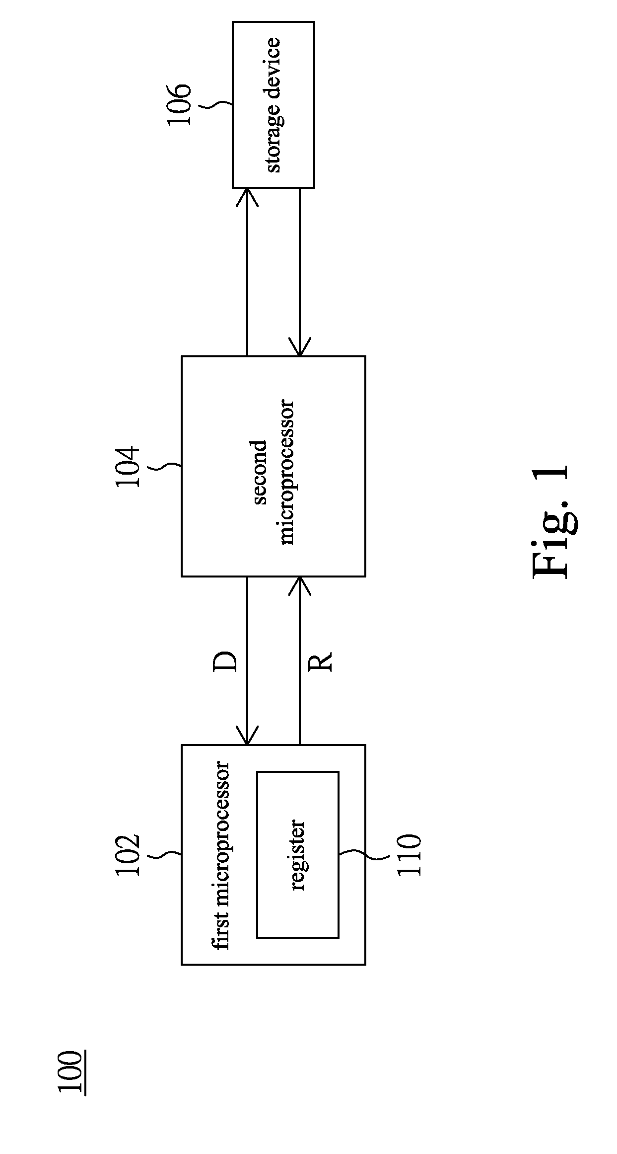
[0013]Referring to FIG. 1 showing a block diagram of a multi-microprocessor system according to a first embodiment of the invention, a multi-microprocessor system 100 comprises a first microprocessor 102, a second microprocessor 104, and a storage device 106. The second microprocessor 104 is coupled to the first microprocessor 102, and is for monitoring the first microprocessor 102.
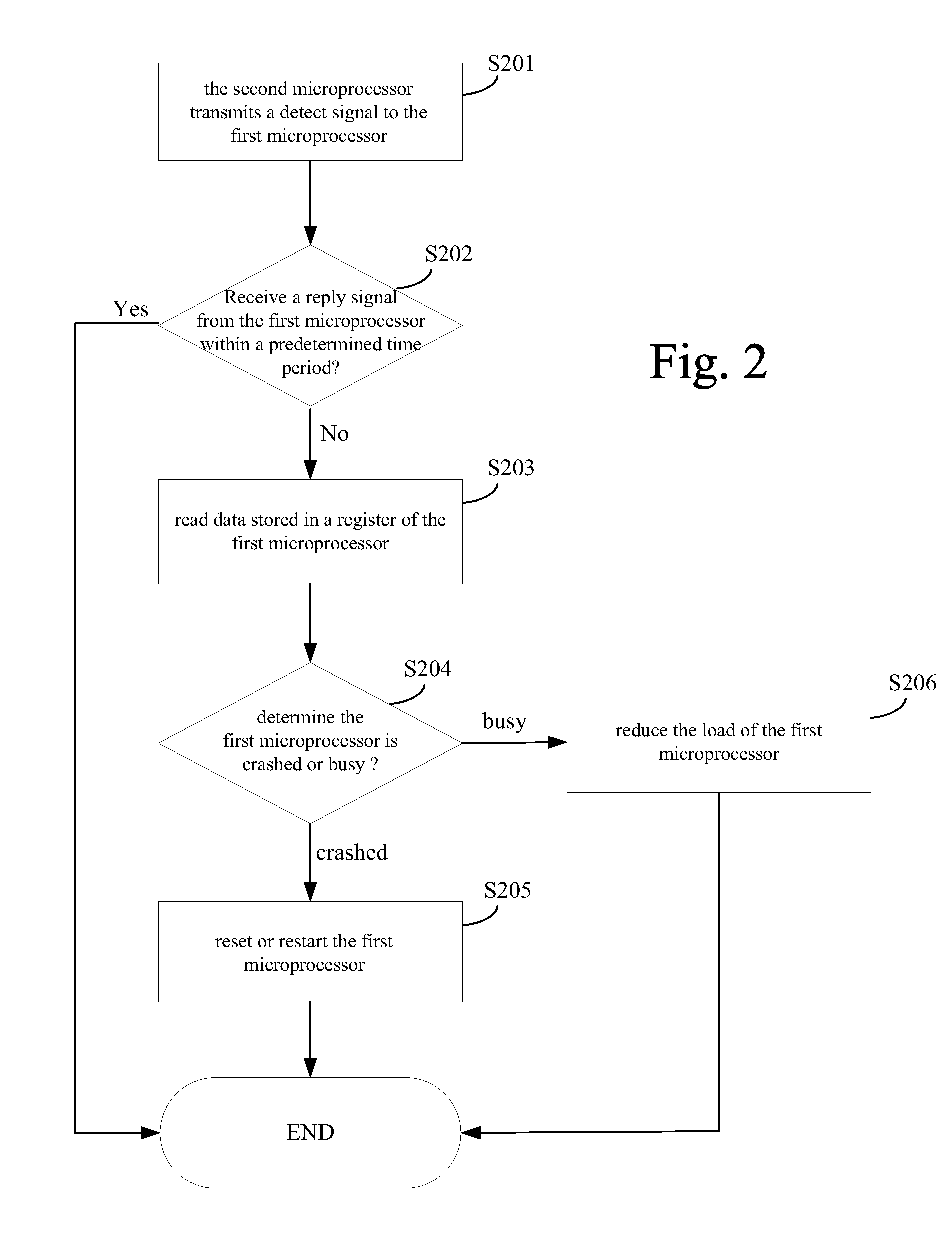
[0014]Please refer to FIG. 2. FIG. 2 shows a flow diagram of a control method of the multi-microprocessor system shown in FIG. 1. When monitoring the first microprocessor 102, the second microprocessor 104 transmits a detect signal D to the first microprocessor 102, as shown in step S201. Then, the second microprocessor 104 determines the state of the first microprocessor 102 according to whether it receives a reply signal R from the first microprocessor 102, as shown in step S202. In the event that the second microprocessor 104 does not receive the reply signal R from the first microprocessor 102 after the predetermined time period, the second microprocessor 104 determines the state of the first microprocessor 102 as being crashed or busy. For double check purpose, the second microprocessor 104 can transmit the detect signal D again to the first microprocessor 102 when not receiving the reply signal R from the first microprocessor 102.
[0015]In step S203, the second microprocessor 104 reads data stored in a register 110 of the first microprocessor 102. In step S204, the second microprocessor 104 determines whether the first microprocessor 102 is crashed or busy according to the data in the register 110 of the first microprocessor 102. The register 110 stores operation data of the first microprocessor 102 for example, wherein the operation data is for an operation being performed or to be performed by the first microprocessor 102. By analyzing operation data stored in the register 110, the state of the microprocessor 102 is obtained. The state may include being crashed, busy, and normal, or other special conditions. The second microprocessor 104 determines the current state of the first microprocessor 102 according to data read from the register 110.
[0016]In the event that the second microprocessor 104 determines the first microprocessor 102 as being crashed, the second microprocessor 104 resets or restarts the first microprocessor 102, as shown in step S205.
[0017]According to another exemplary embodiment, in the event that the second microprocessor 104 does not receive the reply signal R from the first microprocessor 102, the second microprocessor 104 directly resets or restarts the first microprocessor 102 without determining whether the first microprocessor 102 is crashed or busy.
[0018]To reset or restart the first microprocessor 102, the second microprocessor 104 duplicates setting values in the first microprocessor 102 to the storage device 106 before resetting or restarting the first microprocessor 102. When the second microprocessor 104 subsequently resets or restarts the first microprocessor 102, the second microprocessor 104 loads the setting values stored in the storage device 106 back into the first microprocessor 102.
[0019]The foregoing setting values include user-defined setting values, for instance. By duplicating the setting values to the storage device 106 and loading the setting values back into the first microprocessor 102, the first microprocessor 102 having been restarted or reset is stored with the same setting values as before being restarted or reset. Thus, after the first microprocessor 102 is restarted or reset, the entire system is restored to user-defined conditions as before the first microprocessor 102 crashed, such that the user does not even experience the crash but smoothly continue in using the system. Further, the setting values may also include variable values of programs executed by the first microprocessor 102 before the first microprocessor 102 crashed. Hence, loaded variable values facilitate the first microprocessor 102 to instantaneously resume an operating state before the crash to complete any unfinished tasks.
[0020]In the event that the state of the first microprocessor 102 is busy, the second microprocessor 104 reduces load from the first microprocessor 102, as shown in step S206. That is, when a utilization ratio of the first microprocessor 102 exceeds a threshold, the second microprocessor 104 transfers and performs a share of task from the first microprocessor 102, or even cancels a share of task of the first microprocessor 102, so as to cut down the load of the first microprocessor 102.
[0021]Reset or restart procedures according to the microprocessor system of the invention and those of a conventional microprocessor system shall be compared below. In a conventional single-microprocessor system, hardware of the entire microprocessor is necessarily reset when a microprocessor crashes, followed by loading program codes to be performed by the microprocessor using a boot loader to complete a reset or restart procedure. However, such reset or restart method results in loss of previous user-defined setting values or operation contents.
[0022]In this embodiment, suppose a micro code of the first microprocessor 102 is stored in the storage device 106 or another storage device (not shown), e.g. a flash memory. The micro code is a code to be executed by the first microprocessor 102 under normal operating conditions. When the second microprocessor 104 resets or restarts the first microprocessor 102, the micro code in the first microprocessor 102 is directly loaded into the first microprocessor 102 from the storage device 106 or the other storage device by means of direct memory access (DMA). To be more exact, in this embodiment, the second microprocessor 104 loads the micro code into the first microprocessor 102 to complete the reset or restart procedure. Thus, time needed to reset or restart the first microprocessor 102 is greatly reduced.
[0023]The aforesaid storage device may be but not limited to a flash memory and an erasable programmable read-only memory (EPROM). The storage device 106 may also be memory devices in other forms. Flash memories and EPROM have characteristics of maintaining integrity of stored data when a power supply is cut off. Thus, the first microprocessor 102 is still capable of restoring those previous setting values before the power supply is cut off, thereby elevating usage convenience.
[0024]The first microprocessor 102 and the second microprocessor 104 may implement a mailbox of a register as a signal transmission medium. In this embodiment, signal transmission between the first microprocessor 102 and the second microprocessor 104 may be accomplished using an interrupt program. Moreover, for merely illustrative purposes but not to limit the invention within, the first microprocessor 102 may be a high-end microprocessor like a 32-bit microprocessor for executing an operating system, whereas the second microprocessor 104 may be a low-end microprocessor like an 8-bit 8051 microprocessor.
[0025]The multi-microprocessor system according to this embodiment may be applied to electronic devices having at least two microprocessors, from digital televisions, multimedia players to handheld electronic devices.
[0026]In one preferred embodiment, the second microprocessor 104 transmits the detect signal D to the first microprocessor 102 after every certain time period. That is, the second microprocessor 104 continually monitors the first microprocessor 102 and detects the state of the first microprocessor 102 at all times. In any event that the first microprocessor 102 crashes or becomes busy, the second microprocessor 104 instantly recognizes the situation, and immediately resets or restarts the first microprocessor 102, or reduces the first microprocessor 102's workload. Therefore, conditions before the crash are restored, or the load of the first microprocessor 102 is reduced, thereby maximizing stability and optimizing performance of the multi-microprocessor system 100.
Example
Second Embodiment
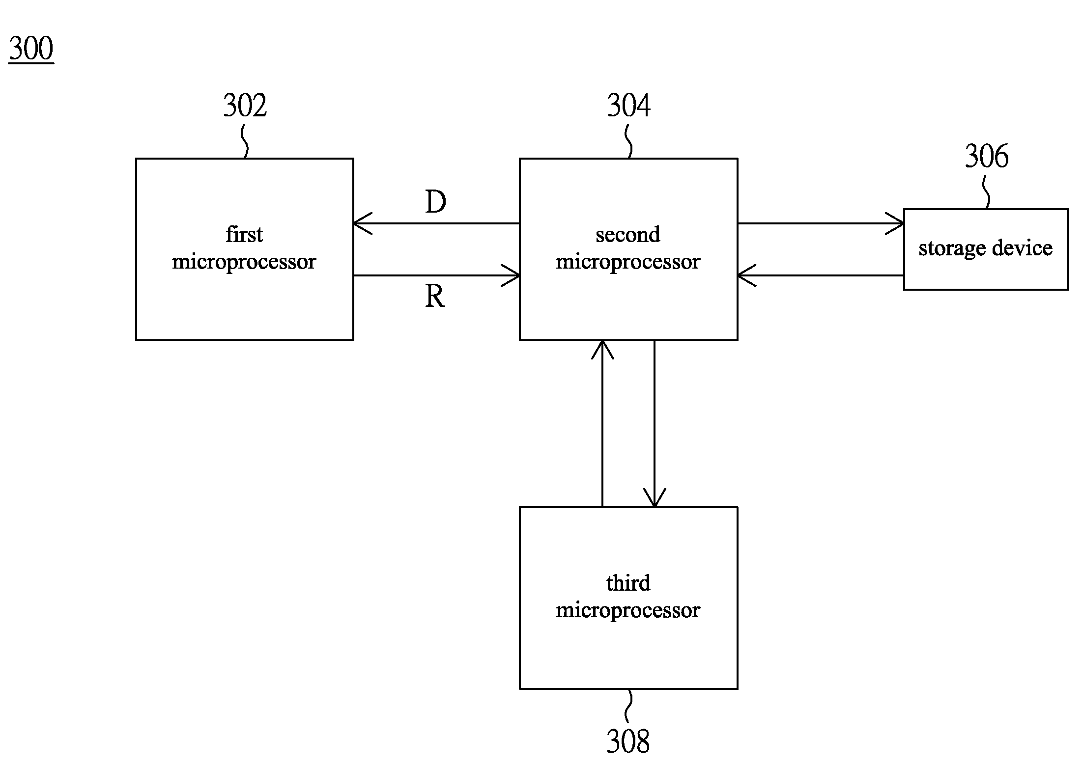
[0027]FIG. 3 shows a block diagram of a multi-microprocessor system according to a second embodiment of the invention. A multi-microprocessor system 300 comprises a first microprocessor 302, a second microprocessor 304, a third microprocessor 308, and a storage device 306. The second microprocessor 304 is coupled to the first microprocessor 302, and is for monitoring the first microprocessor 302.
[0028]A difference in the second embodiment from the first embodiment is that, in the event that the second microprocessor 304 determines the first microprocessor 304 is busy, the second microprocessor 304 transfers a share of task to be executed from the first microprocessor 302 to the third microprocessor 308, so as to reduce the load of the first microprocessor 302.
[0029]For example, the second microprocessor 304 controls the first microprocessor 302 to stop a share of task being performed by the first microprocessor 302. Via controls of the second microprocessor 304, the third microprocessor 308 performs the share of task disrupted from the first microprocessor 302 to reduce the load of the first microprocessor 302. Thus, by reducing the load of the first microprocessor 302, not only performance but also stability of the multi-microprocessor system 300 is optimized.
[0030]According to the above embodiments of the invention, the second microprocessor detects a state of the first microprocessor at all times by continually monitoring the first microprocessor. In the event that the first microprocessor crashes, the first microprocessor is immediately rest or restarted in order to maximize stability of the multi-microprocessor system. In the event that the first microprocessor is busy, the load of the first microprocessor is reduced to effectively optimize performance of the multi-microprocessor system. Further, by storing setting values in the storage device, conditions before the first microprocessor crashed are restored after reset or restart, thereby elevating usage convenience.
[0031]While the invention has been described in terms of what is presently considered to be the most practical and preferred embodiments, it is to be understood that the invention needs not to be limited to the above embodiments. On the contrary, it is intended to cover various modifications and similar arrangements included within the spirit and scope of the appended claims which are to be accorded with the broadest interpretation so as to encompass all such modifications and similar structures.
PUM


Description & Claims & Application Information
We can also present the details of the Description, Claims and Application information to help users get a comprehensive understanding of the technical details of the patent, such as background art, summary of invention, brief description of drawings, description of embodiments, and other original content. On the other hand, users can also determine the specific scope of protection of the technology through the list of claims; as well as understand the changes in the life cycle of the technology with the presentation of the patent timeline. Login to view more.
Similar technology patents
Surveillance system and method having an adaptive sequential probability fault detection test
InactiveUS6892163B1optimize system performance
Owner:INTELLECTUAL ASSETAB
Classification and recommendation of technical efficacy words
- optimize system performance
Surveillance system and method having an adaptive sequential probability fault detection test
InactiveUS6892163B1optimize system performance
Owner:INTELLECTUAL ASSETAB