Bias Current Control Method and Driving Circuit of Operational Amplifier

An operational amplifier, bias current technology, applied in differential amplifiers, DC-coupled DC amplifiers, instruments, etc., can solve problems such as disadvantages of electronic devices, and achieve the effect of saving power consumption, optimizing system performance, and reducing consumption

Active Publication Date: 2015-09-02
NOVATEK MICROELECTRONICS CORP
View PDF4 Cites 0 Cited by
  • Summary
  • Abstract
  • Description
  • Claims
  • Application Information

AI Technical Summary

Problems solved by technology

Since during the T2 period, that is to say, after the slew rate of the operational amplifier 102 is increased until the operational amplifier 102 starts to drive the load LOAD, the operational amplifier 102 does not need to perform any operation, therefore, during the T2 period, the The provided bias current is wasted, resulting in a lot of extra power consumption, which is quite unfavorable for electronic devices that need to save power

Method used


Image

  • Bias Current Control Method and Driving Circuit of Operational Amplifier
  • Bias Current Control Method and Driving Circuit of Operational Amplifier
  • Bias Current Control Method and Driving Circuit of Operational Amplifier

Examples


Embodiment Construction

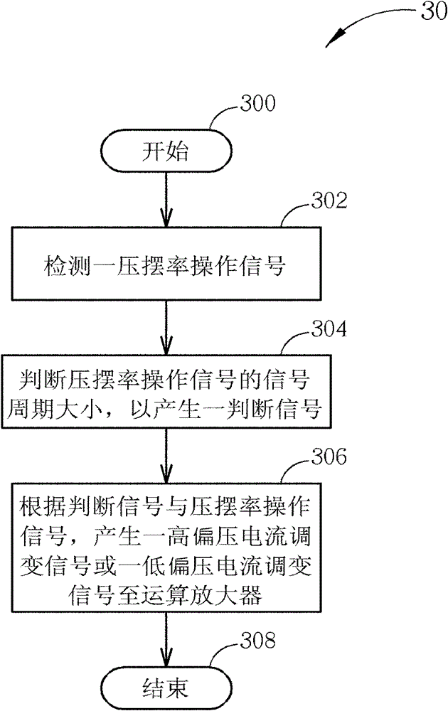
[0031] Please refer to image 3 , image 3 It is a schematic diagram of a bias current control process 30 for an operational amplifier according to an embodiment of the present invention. Process 30 includes the following steps:

[0032] Step 300: Start.

[0033] Step 302: Detect a slew rate operation signal.

[0034] Step 304: Determine the signal period of the slew rate operation signal to generate a determination signal.

[0035] Step 306: Generate a high bias current modulation signal or a low bias current modulation signal to the operational amplifier according to the determination signal and the slew rate operation signal.

[0036] Step 308: End.

[0037] According to the process 30, before the operational amplifier starts to drive the external load, the present invention can determine the signal period size of the detected slew rate operation signal to generate a corresponding determination signal. Next, according to the determination signal, the present invention...


PUM


Abstract

The invention discloses a bias current control method for an operational amplifier. The operation amplifier promotes an internal slew rate through a bias current control system. The bias current control method comprises the following steps of: detecting a slew rate operation signal; judging a signal period of the slew rate operation signal so as to generate a judging signal; and generating a bias modulation signal according to the judging signal and the slew rate operation signal, so that the bias modulation signal can change operation modes of the operational amplifier.

Description

technical field [0001] The present invention relates to a bias current control method for an operational amplifier and a related driving circuit. Background technique [0002] Operational amplifier is an important circuit component in various electronic circuits. Circuit designers can use operational amplifiers to achieve different operational functions. For example, in the driving circuit of the liquid crystal display, the operational amplifier is often used as an output buffer, which charges and discharges the load (ie the liquid crystal) according to the analog signal output by the digital-to-analog converter of the previous stage, so as to drive the liquid crystal display. on the corresponding pixel unit. However, with the increase in the size and resolution of the liquid crystal display, the amount of data output by the driving circuit of the liquid crystal display per unit time is also increasing. Therefore, the response speed of the operational amplifier, that is, t...

Claims


Application Information

Patent Timeline
Patent Type & Authority Patents(China)
IPC IPC(8): H03F3/45G09G3/36
Inventor 洪炜翔林家弘
Owner NOVATEK MICROELECTRONICS CORP
Why Eureka
Try Eureka