Variable ice storage assembly and method of use

a technology refrigerator, which is applied in the field of variable ice storage assembly within the refrigerator, can solve the problems of consumers' ice staleness, and achieve the effect of lowering the level of ice sensed

Active Publication Date: 2009-08-27
WHIRLPOOL CORP
View PDF22 Cites 58 Cited by
  • Summary
  • Abstract
  • Description
  • Claims
  • Application Information

AI Technical Summary

Benefits of technology

[0010]The storage assembly includes first and second insert portions positioned adjacent respective opposing side walls of the storage assembly. The storage assembly can be utilized in a non-reflecting configuration when the first and second insert portions remain empty, or a reflecting configuration when first and second mirrored inserts are positioned in the first and second insert portions respectively. The storage assembly is positioned between an infrared (IR) emitter located on a first inside wall of the refrigerator and a receiver positioned on an opposing inside wall of the refrigerator. When the storage assembly is in the non-reflecting configuration, an emitted IR beam travels in a direct line to the receiver of the overall IR sensor. Any interruption of the beam by ice at a particular level within the storage assembly signals the ice maker to stop ice production. When the storage assembly is in the reflectin...

Problems solved by technology

This leads to the problem of ice staleness for consumers who have relatively low ice consumption needs.
However, Cole and Nelson e...

Method used


Image

  • Variable ice storage assembly and method of use
  • Variable ice storage assembly and method of use
  • Variable ice storage assembly and method of use

Examples


Embodiment Construction

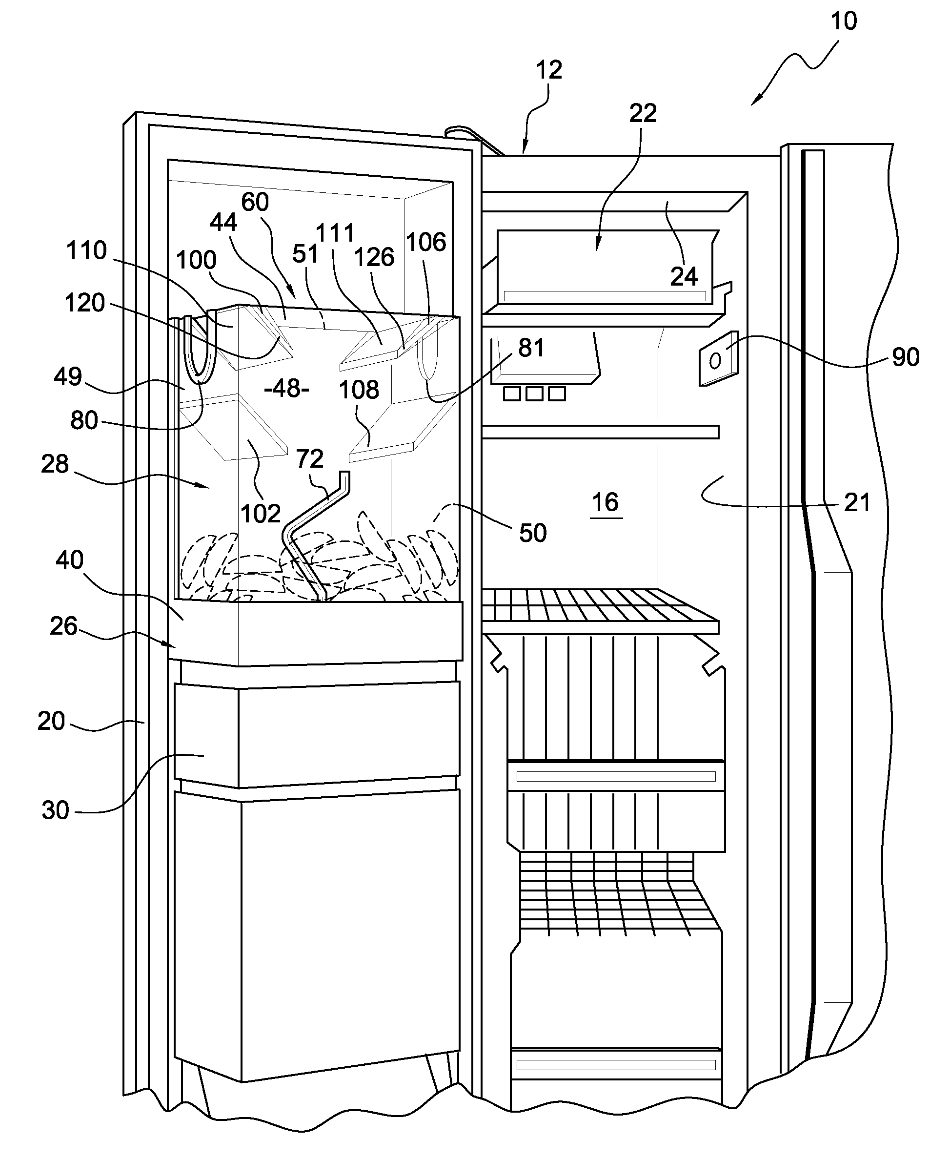
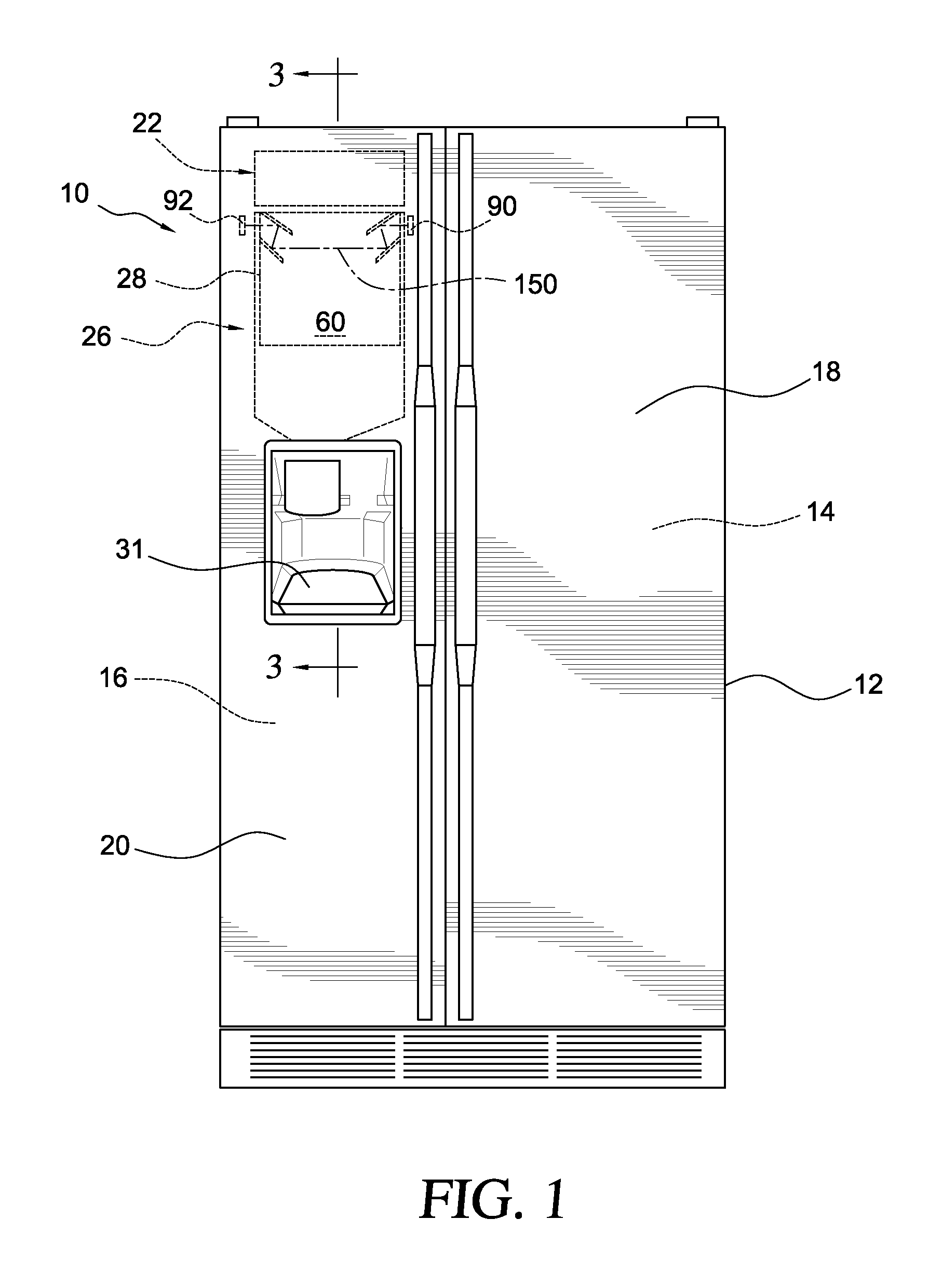
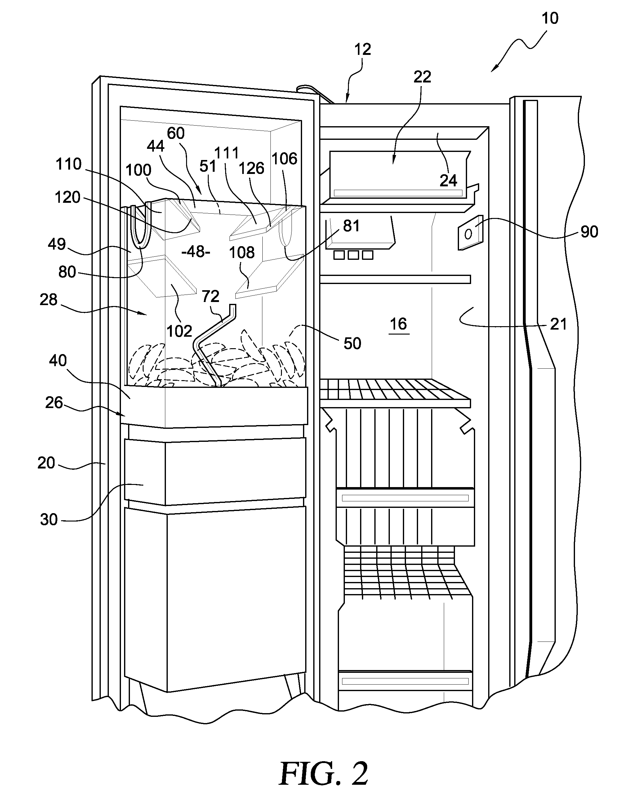
[0017]With initial reference to FIGS. 1 and 2, a refrigerator 10, comprising a side-by-side fresh food / freezer configuration, includes a cabinet 12 forming a fresh food compartment 14 and a freezer compartment 16. Both the fresh food compartment 14 and the freezer compartment 16 are provided with access openings. A fresh food door 18 and a freezer door 20 are hingedly mounted to the cabinet 12 for closing the access openings in a manner well known in the art.

[0018]An ice making assembly 22 is disposed within the freezer compartment 16, such as being mounted to the inside surface of a top wall 24 of the freezer compartment 16 as shown. Regardless, at this point, is should be recognized that ice making assembly 22 can be mounted at a wide range of locations in freezer compartment 16. Preferably, ice maker assembly 22 is a conventional ice making apparatus which forms crescent shaped ice pieces as depicted in FIG. 3. The ice makers disclosed in U.S. Pat. Nos. 4,649,717 and 5,160,094, h...


PUM


Abstract

A variable ice storage assembly for a refrigerator includes a storage cavity adapted to receive ice from an ice maker. The storage assembly is positioned between a light emitter and a receiver of an ice level sensor. The storage assembly can be utilized in a non-reflecting configuration wherein the ice level sensor functions in a standard manner, or a reflecting configuration wherein the sensing level is effectively lowered within the storage assembly. In the reflecting configuration, first and second mirrored inserts, supported by respective insert portions on the storage assembly, cooperate with first and second reflecting plates on the storage assembly to redirect light from the emitter in a circuitous path. A user may position the mirrored inserts at various angles, depending on the level of ice desired within the storage assembly. The storage assembly may be utilized alone, or as in insert within an ice bucket.

Description

BACKGROUND OF THE INVENTION[0001]1. Field of the Invention[0002]The present invention pertains to the art of ice making in refrigerators and, more particularly, to a variable ice storage assembly within a refrigerator, as well as its method of use.[0003]2. Discussion of the Related Art[0004]Automatic ice making systems for use in domestic refrigerators is well known. A typical ice making system includes an ice maker mounted within the freezer compartment of the refrigerator and an ice storage receptacle or bin supported beneath the ice maker for receiving the formed ice from the ice maker. The ice maker is commonly mounted within the freezer compartment adjacent the side or rear wall of the freezer compartment such that water and power can be readily supplied to the ice maker. The ice storage receptacle is supported by a shelf or other structure arranged beneath the ice maker within the freezer compartment. The ice storage receptacle generally extends across a significant portion of...

Claims


Application Information

Patent Timeline
IPC IPC(8): F25C5/18A47B96/04G08B21/00
CPCF25C5/187F25C2700/02F25C2600/04F25C2400/10
Inventor SMITH, LINDSEY A.FULTON, TIMOTHY A.
Owner WHIRLPOOL CORP
Why Eureka
Try Eureka