Contact lens for three dimensional visualization

a three-dimensional visualization and contact lens technology, applied in the field of eyewear, can solve the problems of inconvenient carrying and keeping track of the viewer, inability to complete the experience of virtual world, and inability to move the viewer

Inactive Publication Date: 2009-08-27
UNIV OF WASHINGTON
View PDF15 Cites 48 Cited by
  • Summary
  • Abstract
  • Description
  • Claims
  • Application Information

AI Technical Summary

Problems solved by technology

However, current stereoscopic viewing technology usually requires the use of bulky devices such as 3D viewing glasses, which are often inconvenient for a viewer to carry around and keep track of.
In addition, the current external stereoscopic viewing devices, such as glasses, limit the mobility of the viewer and, therefore, do not allow a complete experience in a virtual world.

Method used


Image

  • Contact lens for three dimensional visualization
  • Contact lens for three dimensional visualization
  • Contact lens for three dimensional visualization

Examples


Embodiment Construction

[0015]Two representative embodiments of the present invention are described with reference to FIGS. 1-4.

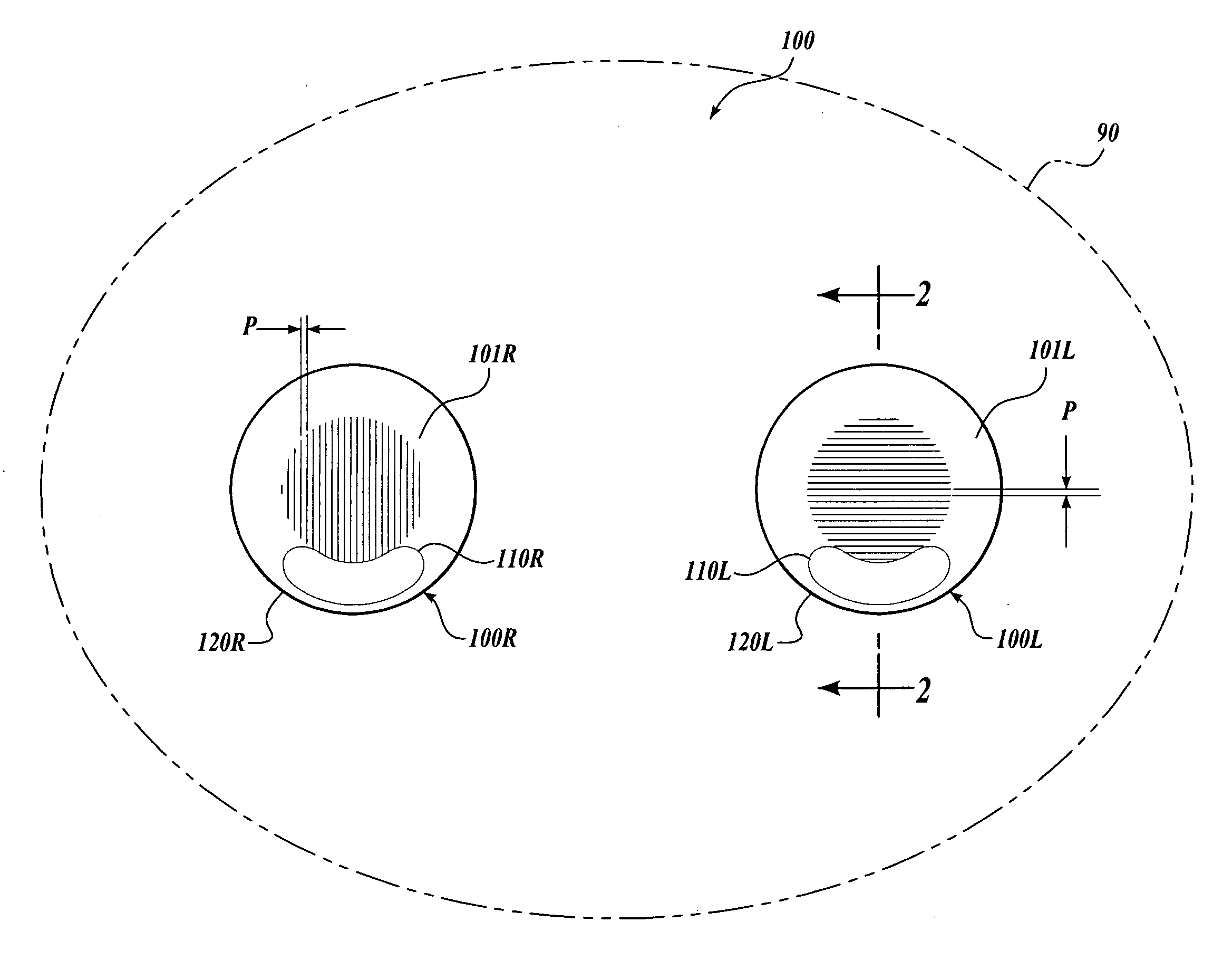
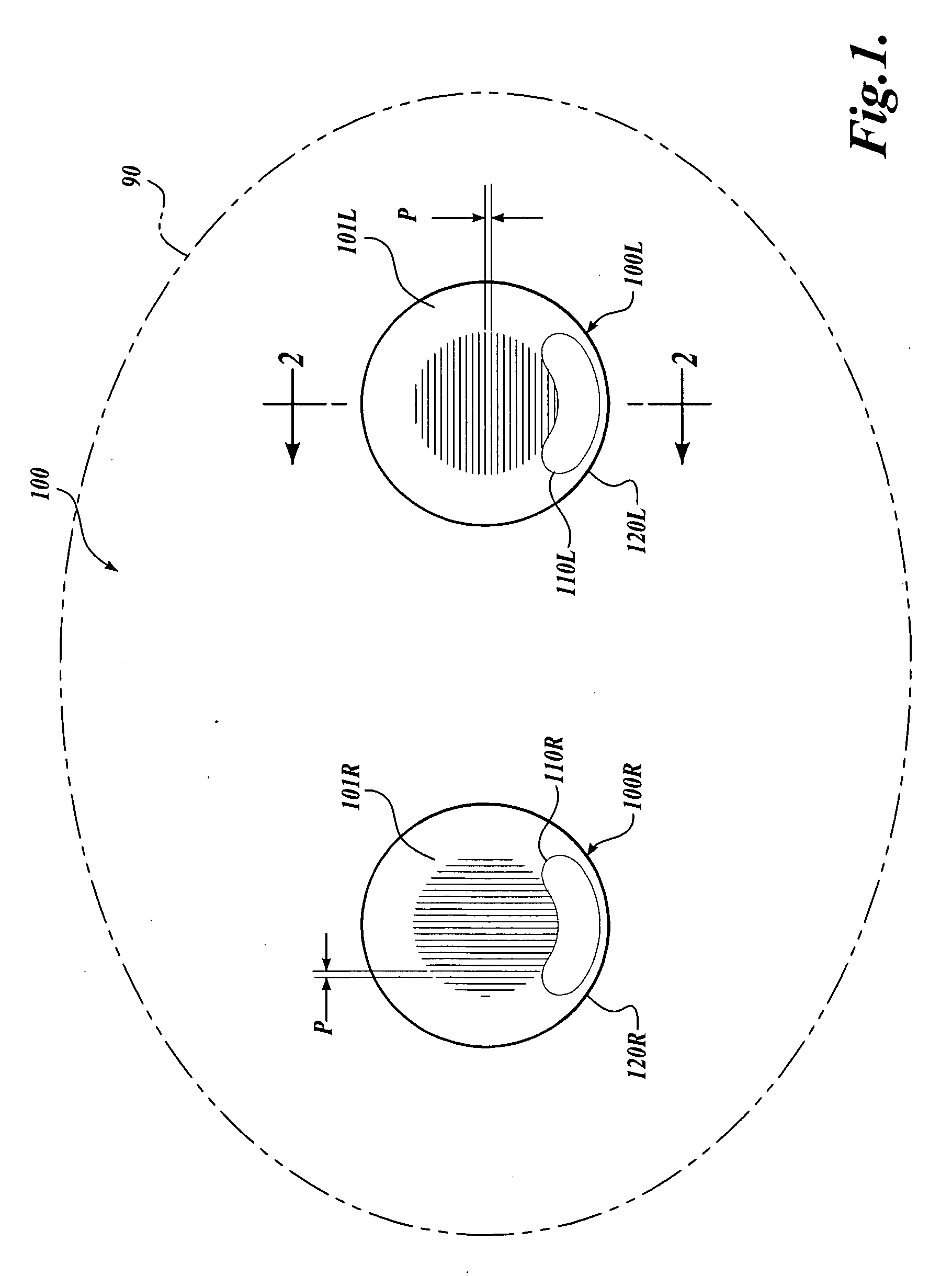
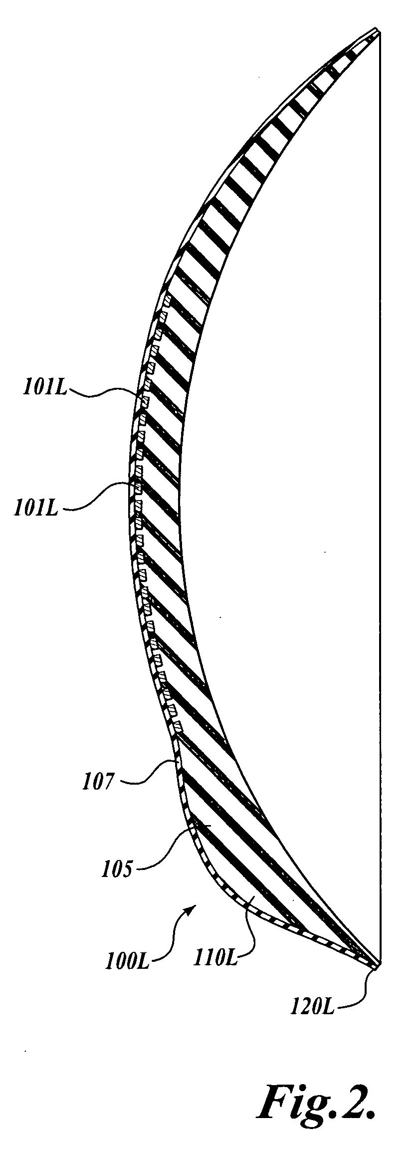
[0016]FIG. 1 shows schematically a contact lens set 100 on a viewer 90 (in phantom). The contact lens set 100 comprises a left contact lens 100L and a right contact lens 100R, each equipped with a linear polarizer portion, as discussed below. The polarization direction of the left contact lens 100L is approximately orthogonal to that of the right contact lens 100R. Each linear polarizer comprises a set of parallel metal lines or wires 101L, 101R produced on the surface of the lens 100L, 100R or embedded in the lens substrate. The parallel lines or wires 101L and 101R have sub-wavelength pitch P. As used herein, “sub-wavelength pitch” means that the distance between neighboring lines or wires of the polarizer is generally less than the smallest wavelength of the received light that is of interest to the user. Preferably, the pitch is less than about one-fifth of the smallest wavele...


PUM


Abstract

A contact lens set for stereoscopic visualization includes a left contact lens comprising a first lens substrate incorporating a first polarizer, and a right contact lens comprising a lens substrate incorporating a second polarizer. The first polarizer comprises a first plurality of parallel lines having sub-wavelength pitch and oriented in a first direction. The second polarizer comprises a second plurality of parallel lines having sub-wavelength pitch and oriented in a second direction. The left contact lens and the right contact lens each comprises a rotational stabilization means, such that, during use, the first direction is adapted to orient in an approximately orthogonal direction to the second direction. In another embodiment, a contact lens set for stereoscopic visualization includes a left contact lens and a right contact lens, each coded with different colors.

Description

CROSS-REFERENCE TO RELATED APPLICATION[0001]This application claims the benefit of Provisional Application No. 61 / 026,069, filed Feb. 4, 2008, the disclosure of which is incorporated herein by reference in its entirety.BACKGROUND[0002]This invention is in the field of eyewear, and more particularly in the field of eyewear for stereoscopic or three-dimensional visualization.[0003]Because the eyes of humans are in different positions on the head, they perceive slightly different views. This is the basis of stereopsis, the process by which the brain exploits the parallax due to the different views from the eye to gain different perception and estimate the distance to objects. Based on the same principle, parallax has been exploited in the engineering of devices for stereoscopic visualization.[0004]A common method for producing stereoscopic images for a viewer is to project two sets of images, wherein the projected images are filtered such that one set of images is linearly polarized in...

Claims


Application Information

Patent Timeline
Patent Type & Authority Applications(United States)
IPC IPC(8): G02B27/22G02B27/26G02C7/04G02B30/25
CPCG02B27/26G02C7/021G02C7/12G02C7/048G02C7/04G02B30/25
Inventor AMIRPARVIZ BABAK
Owner UNIV OF WASHINGTON
Why Eureka
Try Eureka