Tree position adaptive soft output m-algorithm receiver structures

Active Publication Date: 2009-08-27
NTT DOCOMO INC
View PDF59 Cites 32 Cited by
  • Summary
  • Abstract
  • Description
  • Claims
  • Application Information

AI Technical Summary

Problems solved by technology

However, the MaxLogMAP-based inner decoder also becomes computationally intractable as N and b increase.
As a result, they can yield drastic reductions in complexity by proper choice of the M parameter, at a cost in bit-error-rate performance.
As a result, these methods resort to h

Method used


Image

  • Tree position adaptive soft output m-algorithm receiver structures
  • Tree position adaptive soft output m-algorithm receiver structures
  • Tree position adaptive soft output m-algorithm receiver structures

Examples


Embodiment Construction

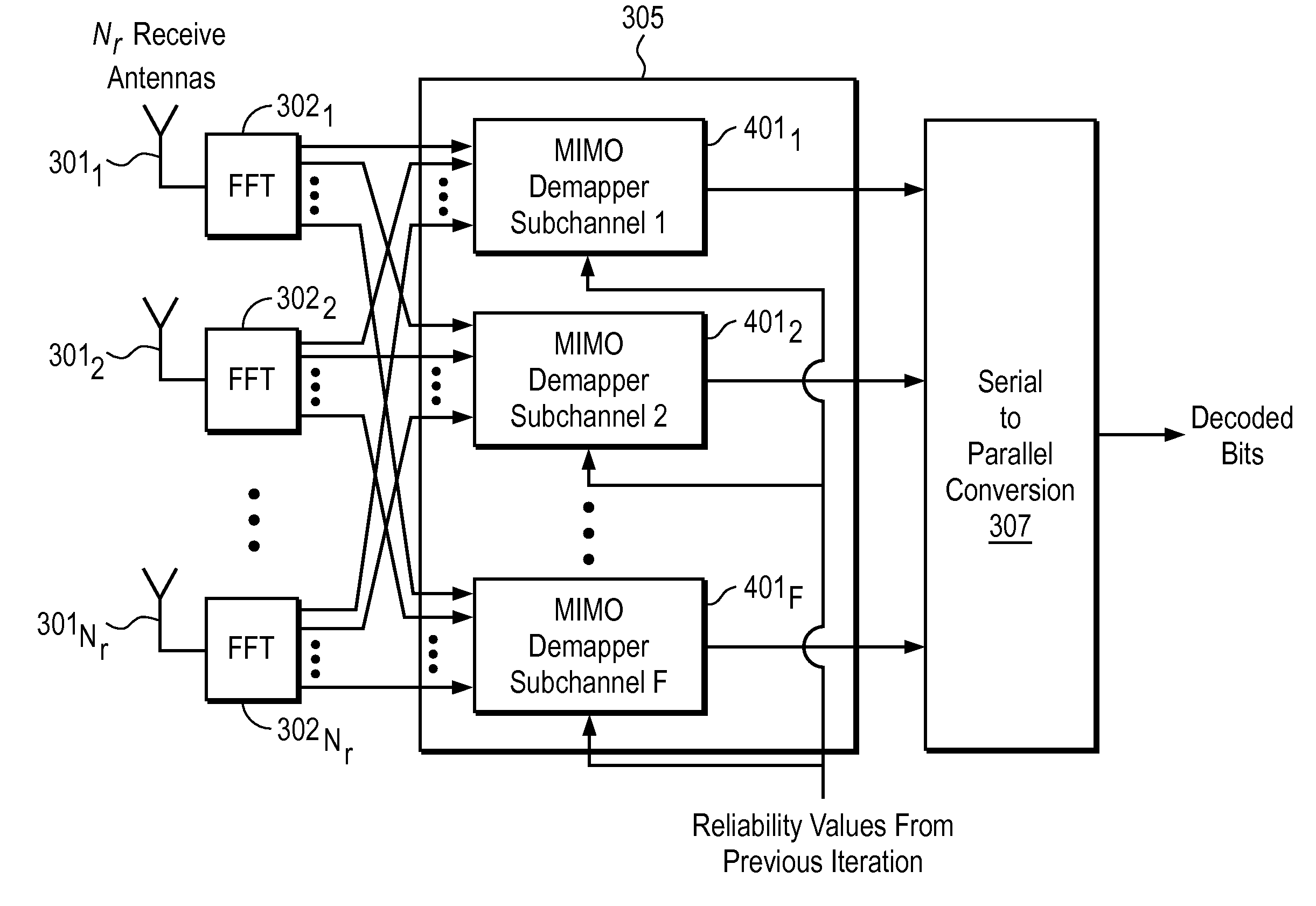
[0026]Methods and apparatuses are disclosed for adaptive reduced complexity receiver structures. In one embodiment, the disclosed techniques deal with receiver complexity reduction for MIMO / OFDM / BICM / ID. The disclosed techniques can also be used with MIMO / OFDM / BICM / ID systems that also employ an inner orthogonal or quasi-orthogonal space-time block code. Also, the transmit antennas need not be collocated, although, typically they are collocated.

[0027]In one embodiment, a detection process is associated with the aforementioned transmission systems. This may consist of an inner / outer decoder structure that may also exploit iterative (turbo-like) decoding, where both the inner decoder (MIMO demapper) and the outer decoder perform soft-in soft-out (SISO) detection / decoding. One system component contributing to the complexity is typically the inner decoder, referred to as a joint demapper.

[0028]One class of inner-decoder algorithm on which the invention can be applied is the reduced-comp...


PUM


Abstract

A method and apparatus for tree position adaptive SOMA receiver structures are disclosed herein. In one embodiment, a device for use in a wireless communication system comprises a receiver to receive information-bearing signals from the transmitter wirelessly transmitted using OFDM and bit interleaved coded modulation, where the receiver includes an inner decoder structure having a soft output M-algorithm (SOMA) based multiple-in multiple-out (MIMO) joint demapper that uses a SOMA-based MIMO detection process to perform joint inner demapping over each tone, and wherein the SOMA-based MIMO joint demapper is operable to search a detection tree for each tone using a tree-search symbol order that is adapted for each tone based on channel state information and extrinsic information from the outer decoder, where only a number of best alternatives from every level of the tree are expanded.

Description

PRIORITY[0001]The present patent application claims priority to and incorporates by reference the corresponding provisional patent application Ser. No. 61 / 031,077, titled, “Tree Position Adaptive Soft Output M-algorithm Receiver Structures for MIMO / OFDM / QAM Systems with BICM / ID,” filed on Feb. 25, 2008.FIELD OF THE INVENTION[0002]The present invention relates to the field of adaptive reduced-complexity receiver structures for receiving information over wireless systems with multiple transmit antennas and, potentially, multiple receive antennas; more particularly, the present invention relates to, in the baseline system, the case where the transmit antennas are collocated at the same base station.BACKGROUND OF THE INVENTION[0003]Future wireless systems require efficient utilization of the radio frequency spectrum in order to increase the data rate achievable within a given transmission bandwidth. This can be accomplished by employing multiple transmit and receive antennas combined wi...

Claims


Application Information

Patent Timeline
IPC IPC(8): H04L23/02
CPCH04L1/005H04L1/0059H04L1/0071H04L1/0631H04L1/0656H04L2025/03426H04L25/03171H04L25/03203H04L25/03216H04L25/03318H04L27/2647H04L25/0204
Inventor BURSALIOGLU, OZGUNPAPADOPOULOS, HARALABOSSUNDBERG, CARL-ERIK W.
Owner NTT DOCOMO INC
Why Eureka
Try Eureka