Time-Shifting and Chase-Play for an IPTV System

Active Publication Date: 2009-08-27
MK SYST USA INC
6 Cites 23 Cited by

AI-Extracted Technical Summary

Problems solved by technology

Linear content delivery, in which all channels in a subscription (“program package”) are simultaneously delivered to the set top box (STB), is not suitable for IPTV due to the limited bandwidth. xDSL connection capacity vari...

Method used

[0044]This procedure could also be run only on an “as needed” basis (i.e. the connection would not be automatically set up at registration, but only when access to the IPTV MW AS is required), but the preferred alternative is that the connection is established immediately after the STB/MS registers. This is so that the delay in setting up this connection can be avoided at a time when interaction with the IPTV MW AS is required.
[0064]The above desc...

Abstract

A system and method for time-shifting and chase-play for an IPTV system. A control channel is established between an originating user's set top box (STB) and an IPTV Application Server (IPTV-AS) utilizing SIP signaling over an IP Multimedia Subsystem. For time-shifting, the STB sends a start time-shifting command to the IPTV-AS over the control channel, and the IPTV-AS sends a start recording command to a Network Private Video Recorder (N-PVR). When the user is ready to resume viewing, the STB sends a start chase-play command to the IPTV-AS to establish a unicast channel. The IPTV-AS sends a playback command to the N-PVR to begin playback of the time-shifted content.

Application Domain

Television system detailsColor television details +2

Technology Topic

Application serverStart time +5

Image

  • Time-Shifting and Chase-Play for an IPTV System
  • Time-Shifting and Chase-Play for an IPTV System
  • Time-Shifting and Chase-Play for an IPTV System

Examples

  • Experimental program(1)

Example

[0034]By way of background to the preferred embodiment, the following is a brief description of how the IP Multimedia Subsystem (IMS) fits into the mobile network architecture in the case of a GPRS/PS access network. Call/Session Control Functions (CSCFs) operate as SIP proxies within the IMS. The 3GPP architecture defines three types of CSCFs: the Proxy CSCF (P-CSCF) which is the first point of contact within the IMS for a SIP terminal; the Serving CSCF (S-CSCF) which provides services to the user that the user is subscribed to; and the Interrogating CSCF (I-CSCF) whose role is to identify the correct S-CSCF and to forward to that S-CSCF a request received from a SIP terminal via a P-CSCF.
[0035]A user registers with the IMS using the specified SIP REGISTER method. This is a mechanism for attaching to the IMS and announcing to the IMS the address at which a SIP user identity can be reached. The user receives a unique Uniform Resource Identifier (URI) from the S-CSCF to be used when it initiates a dialog. In 3GPP, when a SIP terminal performs a registration, the IMS authenticates the user, and allocates a S-CSCF to that user from the set of available S-CSCFs. Whilst the criteria for allocating S-CSCFs is not specified by 3GPP, these may include load sharing and service requirements. It is noted that the allocation of an S-CSCF is key to controlling (and charging for) user access to IMS-based services. Operators may provide a mechanism for preventing direct user-to-user SIP sessions that would otherwise bypass the S-CSCF.
[0036]During the registration process, it is the responsibility of the I-CSCF to select an S-CSCF if one is not already selected. The I-CSCF receives the required S-CSCF capabilities from the home network's Home Subscriber Server (HSS), and selects an appropriate S-CSCF based on the received capabilities. (It is noted that S-CSCF allocation is also carried out for a user by the I-CSCF in the case where the user is called by another party, and the user is not currently allocated an S-CSCF.) When a registered user subsequently sends a session request (e.g. SIP INVITE) to the IMS, the request will include the P-CSCF and S-CSCF URIs so that the P-CSCF is able to forward the request to the selected S-CSCF. This applies both on the originating and terminating sides (of the IMS). (For the terminating call the request will include the P-CSCF address and the User Equipment (UE) address.)
[0037]Within the IMS service network, Application Servers (ASs) are provided for implementing IMS service functionality. ASs provide services to end-users in an IMS system, and may be connected either as end-points over the 3GPP defined Mr interface, or “linked in” by an S-CSCF over the 3GPP defined ISC interface. In the latter case, Initial Filter Criteria (IFC) are used by an S-CSCF to determine which ASs should be “linked in” during a SIP Session establishment. Different IFCs may be applied to different call cases. The IFCs are received by the S-CSCF from an HSS during the IMS registration procedure as part of a user's User Profile (UP). Certain ASs will perform actions dependent upon subscriber identities (either the called or calling subscriber, whichever is “owned” by the network controlling the AS). For example, in the case of call forwarding, the appropriate (terminating) application server will determine the new terminating party to which a call to a given subscriber will be forwarded.
[0038]The preferred embodiment to be described below relates to an IMS-enabled control channel for an IPTV set top box (STB). The control channel is set up using standard IMS procedures and is later used to send control messages to the IPTV applications server, as well as to deliver personalized content, such as advertisements, voting responses, personalized voting triggers and targeted interactive events.
IMOD Connection to IPTV AS
[0039]It should be noted that the STB is described as a single unit in the following. The sequences of the figures show division of the STB into an IMOD and a MTRX but the interaction between these is not described as this is not directly relevant to the inventive concepts described.
[0040]When the STB starts, it first registers on the IMS network using the IMS Private ID (IMPI—the private address of the STB) of the Identity and IMS Module (IMOD) in the authorization header, and the default ‘family STB’ public address in the “From” and “To” headers (as in the normal SIP REGISTER message). Both IMPUs representing the Media Transmitter/Receivers (MTRXs) and IMPUs representing users may register. For personalisation of services, a “User Connection to IPTV MW AS” use routine is executed.
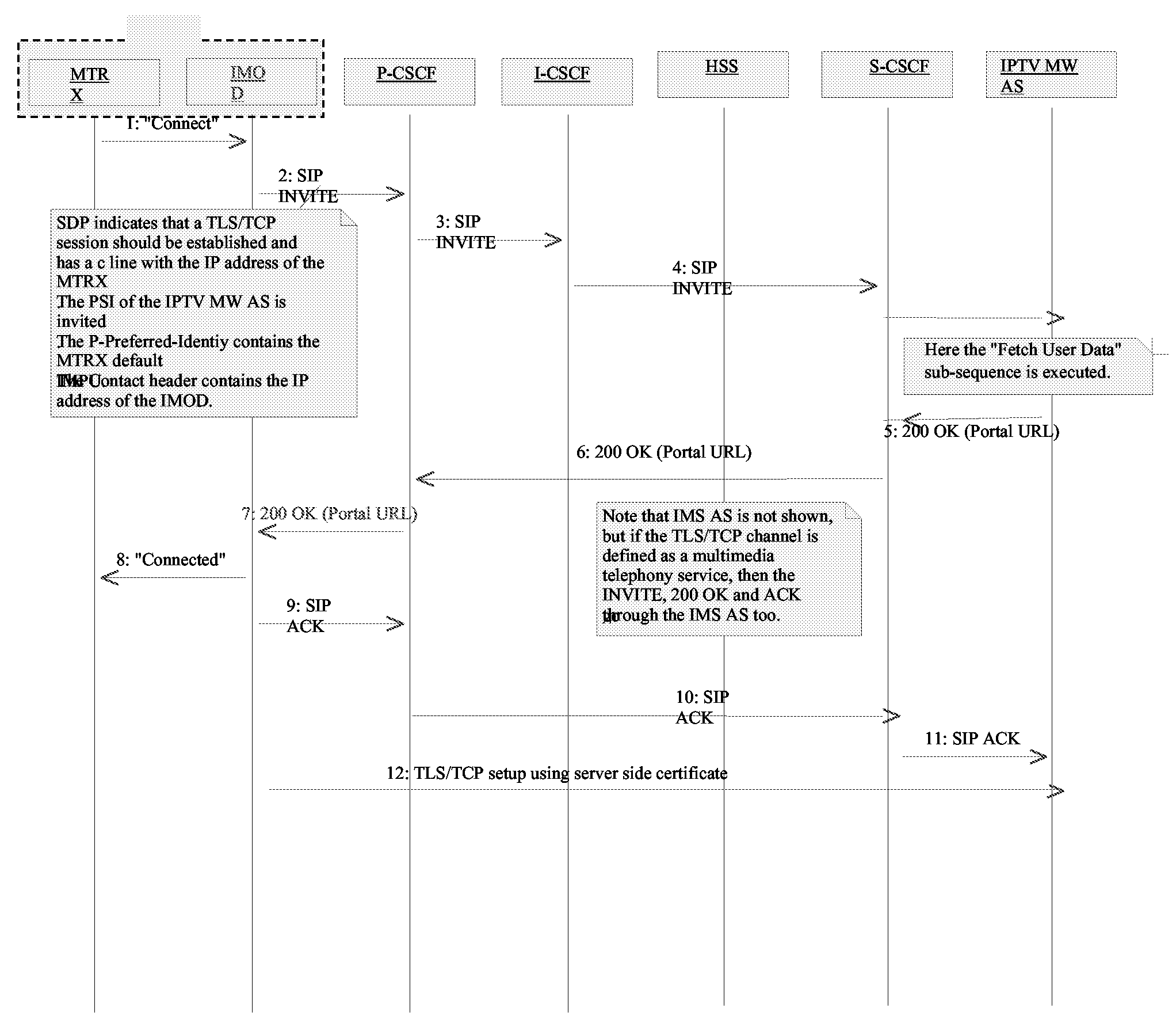
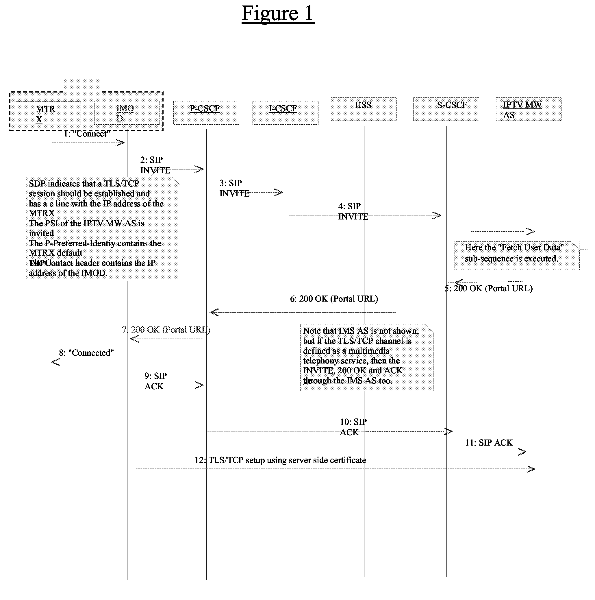
[0041]Once the STB is registered, it establishes a secure TCP/TLS connection with the IPTV AS, using a SIP INVITE message. The procedure, as schematically indicated in FIG. 1, is as follows (with reference to the numbers used in the figure):
1. The MTRX (the media end point of the STB) indicates to the IMOD (the Authentication/ISIM carrier part of the STB) that a connection to the IPTV MW AS should be established. The differentiation between the IMOD and the MTRX is optional, and can be seen as an STB internal realization. An STB not having this differentiation would behave identically in relation to the IMS network.
2. The IMOD sends a SIP INVITE message to the P-CSCF. The Public Service Identity of the IPTV MW AS is used to address the IPTV MW AS and may be pre-configured in the ISIM or configured by device management procedures. An SDP description of a TLS/TCP session is included. An alternative procedure would be to use an application framing protocol over the pure TCP/TLS channel, such as MSRP. In this case the SDP description contains MSRP/TLS/TCP instead of only TLS/TCP.
3. The SIP INVITE message is forwarded to the I-CSCF. 3GPP 23.228 describes alternative PSI routing on the terminating side, namely:
a. The I-CSCF interrogates I HSS where the HSS treats every PSI as a “user” and returns routing instructions to the end-point representing the PSI.
b. I-CSCF interrogation to the HSS where the HSS returns the user allocated S-CSCF. The S-CSCF routes the PSI addressed Invite according to IFC information stored per “PSI-subscriber”. The “PSI-subscriber” is assigned an S-CSCF.
c. Sub-domain routing in the I-CSCF where the I-CSCF uses DNS to resolve the PSI into an IP-address for the end-point representing the PSI.
[0042]This solution requires Alternative b.
4. The I-CSCF uses DNS to translate the Public Service Identity to the IP address of the actual server that will handle this user this time (load sharing can be applied here). The S-CSCF then sends the SIP INVITE message to the chosen IPTV MW AS. The IPTV MW AS then executes the “Fetch User Data” sub-sequence.
5. The IPTV MW AS returns a 200 OK response. The URL of the user's TV service portal is included in the SDP, as, for example, an XML body that is interpreted in the STB but not in the intermediate nodes.
6. The S-CSCF forwards the 200 OK response.
7. The P-CSCF forwards the 200 OK response.
8. The IMOD receives the URL of the default user's TV service portal (i.e. the portal associated with the IMPU of the MTRX), and it is included in the SDP. This information may be included as an XML body in the 200 OK message, but other means are also possible.
9. The IMOD sends a SIP ACK response.
10. The P-CSCF forwards the SIP ACK response.
11. The S-CSCF forwards the SIP ACK response.
12. The IMOD sets up a TLS/TCP connection to the IPTV MW AS using a server side certificate.
[0043]This procedure can also be expanded to add distribution of keys for service protection (a.k.a. conditional access) if the service protection in the system is based on ciphering the content streams. This would involve additional steps after the last step above in which, for example, the keys could be fetched via HTTP. If the different users have different channel bundles, then that type of step would also be needed after the “User Connection, Local User” procedure.
[0044]This procedure could also be run only on an “as needed” basis (i.e. the connection would not be automatically set up at registration, but only when access to the IPTV MW AS is required), but the preferred alternative is that the connection is established immediately after the STB/MS registers. This is so that the delay in setting up this connection can be avoided at a time when interaction with the IPTV MW AS is required.
[0045]A new control channel is established for each MTRX that is to be connected to the IMOD, as described in the “IMS IPTV Architecture Study” (“Rechon Architecture”, EAB-05:045608, Rev A, Dec. 22, 2005).
[0046]The described control channel enables a plethora of functionalities, like remote control on the IPTB STB, as described in “IMS IPTV Architecture Study”, EAB-06:001721, Rev A, Feb. 8, 2006, or the user cases described in next section.
[0047]When the STB starts, it first registers on the IMS network using the IMS Private ID (IMPI—the private address of the STB) of the Identity and IMS Module (IMOD) in the authorization header, and the default ‘family STB’ public address in the “From” and “To” headers (as in the normal SIP REGISTER message). Once the STB has been registered, it establishes a secure TCP/TLS connection with the IPTV AS using a SIP INVITE message.
STB Initiated Time-Shift
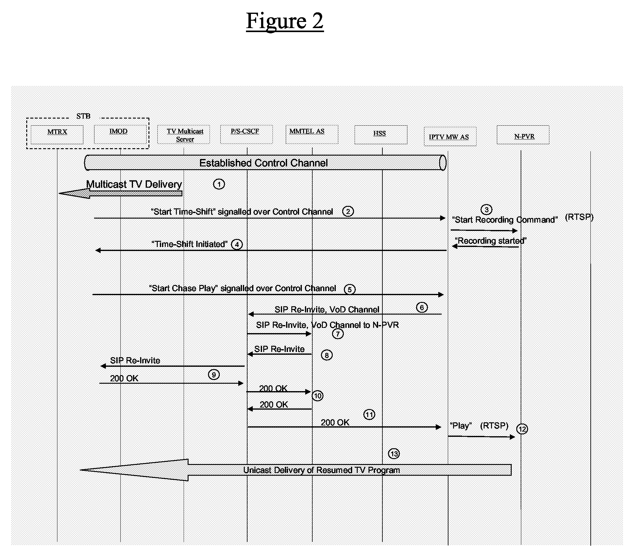
[0048]In the event that the user requires time shifting of the content to begin, the following IMS based method for switching between multicast and unicast delivery of content can be initiated by the STB. The procedure, as schematically indicated in FIG. 2, is as follows (with reference to the numbers used in the figure):
1) A control channel is established between the STB and the IPTV-AS by the procedure described above with reference to FIG. 1. At this point the STB is receiving content that is delivered by multicast.
2) The user decides to start the Time-Shift function due to an event taking place in the home requiring the user's full attention, such as the ringing of a door-bell, the arrival of an ordered pizza, or the imminent start of booked laundry time, etc. The STB generates a “Start Time-Shift” command and sends this over the control channel to the IPTV-AS. The exact procedure and syntax of the command is a matter between the STB and the IPTV-AS, and many different variants are possible. The IPTV-AS interprets the command before taking the appropriate action.
3) The IPTV-AS initiates recording of the currently viewed multicast channel. This is possible as the STB always reports which multicast channel it is currently receiving after a channel change has occurred (not shown in the figure). A “Start Recording” command is sent from the IPTV-AS to the N-PVR system. The exact procedure and syntax of the command is a matter between the STB and the IPTV-AS, and many different variants are possible. The IPTV-AS acts as a gateway between the N-PVR system and the STB. This enables STB/IPTV-AS specific user interaction whilst allowing use by operators of many different types of N-PVR system. The adjustment of the required N-PVR procedures and protocols is handled by the IPTV-AS.
4) An indication that the Time-Shift has started is returned to the STB and optionally displayed to the user. The multicast channel may or may not continue to be delivered to the STB after the Time-Shift has started. This is a deployment option.
5) When the user is ready to resume viewing of the time-shifted content, he initiates the Chase Play function and a “Start Chase Play” command is sent from the STB to the IPTV-AS over the control channel. The exact procedure and syntax of the command is a matter between the STB and the IPTV-AS, and many different variants are possible. The IPTV-AS acts as a gateway between the N-PVR system and the STB. This enables STB/IPTV-AS specific user interaction whilst allowing use by operators of many different types of N-PVR system. The adjustment of the required N-PVR procedures and protocols is handled by the IPTV-AS. RTSP is used in the sequence by way of example but the invention is not limited to the use of RTSP.
6) The IPTV-AS sends a SIP INVITE message in the same SIP session as the “Start Chase Play” command that is associated with the control channel. The SIP Re-invite message is a request to establish a unicast channel that will be used to deliver the recorded (time-shifted) content stored in the N-PVR system. As a result the content delivery changes from multicast to unicast delivery with IMS being used to effect this change.
7-8) The SIP INVITE message is transmitted over the ISC and the Multimedia Telephony (MMTEL) AS, MMTel being used as the IMS Communication Service for IPTV in this case, thus resulting in the invocation of the MMTel AS over the ISC. It should however be noted that the method will work with other IMS Communication Services and is not limited to MMTel, MMTel being given merely by way of example. The MMTel AS may invoke supplementary services, such as restriction on the number of concurrent unicast deliveries, but this is not included in the sequence.
9-10) The SIP INVITE message is sent to the STB which acknowledges the request with a 200 OK response to accept the unicast channel invitation.
10, 11) The 200 OK response is sent along the SIP session path to the IPTV-AS.
12) The IPTV AS initiates playback of the recorded content by means of a “Play” command to the N-PVR system. The IPTV-AS acts as a gateway between the Network PVR system and the STB. This enables STB/IPTV-AS specific user interaction whilst allowing use by operators of many different types of N-PVR system. The adjustment of the required N-PVR procedures and protocols is handled by the IPTV-AS. RTSP is used as an example in the sequence but the invention is not limited to RTSP.
13) Unicast delivery is started.
Incoming Call Notification
[0049]This sequence describes how an Incoming Call Notification on a TV-screen and user determined call handling can be implemented for IMS calls to the STB/TV. The call is established to the STB/TV in this scenario, and the STB/TV is also used to notify a user of an incoming call and to allow the user to specify how the call shall be handled. The procedure, as schematically indicated in FIG. 3, is as follows (with reference to the numbers used in the figure):
1) A control channel is established between the STB and the IPTV-AS by the procedure described above with reference to FIG. 1. At this point the STB is receiving content that is delivered by multicast.
2) The I-CSCF in the called subscriber's network (the STB's network) receives a SIP INVITE message from the same IMS network or another IMS network, or from an IMS gateway to another network (e.g. ISDN/PSTN). The I-CSCF returns a 100 Trying response to the sender of the SIP Invite message to stop periodic retransmission of the same SIP INVITE message.
3) I-CSCF uses a Diameter LIR (Location Information Request) to obtain the called subscriber's S-CSCF address and the HSS returns this address in the LIA (Location Information Answer).
4) The SIP INVITE message is sent to the called subscriber's S-CSCF (100 trying response returned by the S-CSCF).
5) The trigger criteria for the called subscriber are stored by the S-CSCF. This IFC contains information about which AS's are to be invoked over the ISC interface. This example shows an incoming call for the MMTel IMS communication service and the MMTel AS is invoked over the ISC. The MMTel AS may invoke supplementary services, such as barring or forwarding of incoming sessions, but this is not included in the sequence.
6) The MMTel AS exposes enabling services towards other AS's to allow these to affect the session set up. The IPTV AS has subscribed to the incoming call event from the MMTel AS, and the service definition of the exposed services is based on the Parlay-X Web Service definitions for Call Control. A Parlay-X “Handle Called Number Request” is sent to the IPTV-AS. It should be noted that a Parlay-X service can also be exposed by an OSA (Open Service Access)/Parlay(-X) gateway that is connected over the ISC (IMS Service Control) interface in the same way as an IMS (IP Multimedia Subsystem) AS. It should further be noted that the IPTV-AS can be connected over the ISC in series with the MMTel AS to perform the Call Notification procedures described below. Whilst this description only refers to the alternative where the Parlay-X Call Control service is exposed by the MMTel AS, it will be appreciated that the invention is not limited to this.
7) An “Incoming Call Notification” command is sent from the IPTV-AS to the STB over the control channel. The exact procedure and syntax of the command is a matter between the STB and the IPTV-AS, and many different variants are possible. The user is given a number of call handling options, such as: [0050] allow call to STB/TV [0051] forward call to voice-mail (multimedia mail) [0052] forward call to another number
The user's choice is returned by the STB to the IPTV-AS. In the following it is assumed that the user chooses to allow the call.
8) The IPTV-AS returns a Parlay-X “Handle Called Number Response” to the MMTel AS with information specifying that the call set up may proceed to the STB.
9) The S-CSCF receives the SIP Invite message from the MMTel AS (MMTel works as a B2BUA in this example). An S-CSCF may perform forking for the contacts registered for one particular Public User Identity (PUI). The STB has a unique PUI in this example and no other SIP UA is allowed to register as a contact for the STB's PUI. The STB may however register as a contact for other user assigned PUIs, and this allows a mobile phone and the STB to register as possible contacts for one particular PUI for example.
10, 11, 12 13) The SIP Invite message is sent to the STB and the STB returns a 180 Ringing response which is relayed along the SIP path.
14, 15, 16, 17) A 200 OK response from the STB indicates that the session has been accepted and that the media plane can be established.
18) The media plane for speech is established and the call proceeds.
PSTN/ISDN Incoming Call Notification
[0053]This sequence describes how an Incoming Call Notification on a TV-screen and user determined call handling can be implemented for PSTN/ISDN phones in the home. It should be noted that the call is not established to the STB/TV in this scenario. The STB/TV is only used to notify a user of an incoming call and to allow the user to specify how the call shall be handled. The procedure, as schematically indicated in FIG. 4, is as follows (with reference to the numbers used in the figure):
1) A control channel is established between the STB and the IPTV-AS by the procedure described above with reference to FIG. 1. At this point the STB is receiving content that is delivered by multicast.
2, 3) An SSF (Service Switching Function) in the called subscriber's network receives an ISUP (ISDN User Part) IAM (Initial Address Message). This triggers the SSF to contact a Service Control Point (SCP) in an IN (Intelligent Network) architecture.
[0054]An OSA/Parlay GW (Gateway) plays the role of an SCP towards the SSF, but allows AS's to take the real decisions on how to handle calls. Many different variants on INAP protocols exist, e.g. CS1, CS2, CAP, etc. This description is given with reference to an IDP (Initial Detection Point) operation invocation which can be found in CAP (CAMEL Application Part), although it will be appreciated that the invention is not limited to this particular type of INAP (Intelligent Network Application Part).
4) The IDP is translated into the Parlay-X Web service definition for Call Control. A Parlay-X “Handle Called Number Request” is sent to the IPTV-AS. This is the same message that was sent in the previous sequence from the MMTel IMS AS to the IPTV AS, and enables the IPTV AS to have a common call handling interface for IMS and PSTN/ISDN calls. It should be noted that the IPTV-AS can also be connected as an SCP (Service Control Point) via INAP. This description refers only to the alternative where the Parlay-X Call Control service is used, but the invention is not limited to this.
5) An “Incoming Call Notification” command is sent from the IPTV-AS to the STB over the control channel. The exact procedure and syntax of the command is a matter between the STB and the IPTV-AS, and many different variants are possible. The user is given a number of call handling options, such as: [0055] allow call to STB/TV [0056] forward call to voice-mail (multimedia mail) [0057] forward call to another number
The user's choice is returned by the STB to the IPTV-AS. In the following it is assumed that the user chooses to allow the call.
6) The IPTV-AS returns a Parlay-X “Handle Called Number Response” to the MMTel AS with information specifying that the call set up to the PSTN/ISDN phone may proceed.
7) The OSA/Parlay GW returns the appropriate INAP message to the SSF, e.g. a Continue operation invocation.
8) The SSF sends an ISUP IAM message to the Local Exchange that the user's PSTN/ISDN phone is connected to.
9) A Q.931 ISDN Set-up message is sent to the ISDN phone (only ISDN shown from now on), and is acknowledged by a Call Confirmed message.
10, 11) An ISUP ACM (Address Complete Message) message is sent from the Local Exchange to the SSF (Service Switching Function) and onwards.
12, 13, 14) An alert is forwarded in ISUP CPG (Call Progress).
15, 16, 17) An Answer message is translated into an ISUP ANM (Answer Message).
18) The ISDN/PSTN call is established.
Extended Incoming Call Scenario with Time-shift
[0058]This sequence extends the Incoming Call Notification sequence with Time-Shift functionality. The procedure, as schematically indicated in FIG. 5, is as follows (with reference to the numbers used in the figure):
1) A control channel is established between the STB and the IPTV-AS by the procedure described above with reference to FIG. 1. At this point the STB is receiving content that is delivered by multicast.
2) The I-CSCF in the called subscriber's network (the STB's network) receives a SIP Invite message from the same IMS network or another IMS network, or from an IMS gateway to another network (e.g. ISDN/PSTN). The I-CSCF returns a 100 Trying response to the sender of the SIP Invite message to stop periodic retransmission of the same SIP Invite message.
3) I-CSCF uses a Diameter LIR (Location Information Request) to obtain the called subscriber's S-CSCF address and the HSS returns this address in the LIA (Location Information Answer).
4) The SIP INVITE message is sent to the called subscriber's S-CSCF (100 trying response returned by the S-CSCF).
5) The trigger criteria for the called subscriber are stored by the S-CSCF. This IFC contains information about which AS's that are to be invoked over the ISC interface. This example shows an incoming call for the MMTel IMS communication service and the MMTel AS is invoked over the ISC. The MMTel AS may invoke supplementary services such as barring or forwarding of incoming sessions, but this is not included in the sequence.
6) The MMTel AS exposes enabling services towards other AS's to allow these to affect the session set up. The IPTV AS has subscribed to the incoming call event from the MMTel AS, and the service definition of the exposed services is based on the Parlay-X Web Service definitions for Call Control. A Parlay-X “Handle Called Number Request” is sent to the IPTV-AS. It should be noted that a Parlay-X service can also be exposed by an OSA/Parlay(-X) gateway (OSA=Open Service Access) that is connected over the ISC (IMS Service Control) interface in the same way as an IMS-AS. It should further be noted that the IPTV-AS can be connected over the ISC in series with the MMTel AS to perform the Call Notification procedures described below. Whilst this description only refers to the alternative where the Parlay-X Call Control service is exposed by the MMTel AS, it will be appreciated that the invention is not limited to this.
7) An “Incoming Call Notification” command is sent from the IPTV-AS to the STB over the control channel. The exact procedure and syntax of the command is a matter between the STB and the IPTV, and many different variants are possible. The user is given a number of call handling options, such as: [0059] allow call to STB/TV [0060] forward call to voice-mail (multimedia mail) [0061] forward call to another number [0062] allow call and start Time-Shift
The user's choice is returned by the STB to the IPTV-AS. In this example the user chooses to allow the call and to start Time-Shift.
8) The IPTV-AS initiates recording of the currently viewed multicast channel. This is possible since the STB always reports which multicast channel it is currently receiving after a channel change (not shown in the sequences). A “Start Recording” command is sent from the IPTV-AS to the N-PVR system. The IPTV-AS acts as a gateway between the Network PVR system and the STB. This enables STB/IPTV-AS specific user interaction whilst allowing use by operators of many different types of N-PVR system. The adjustment of the required N-PVR procedures and protocols is handled by the IPTV-AS.
9) The IPTV-AS returns a Parlay-X “Handle Called Number Response” to the MMTel AS with information specifying that the call set up may proceed to the STB. The S-CSCF receives the SIP INVITE message from the MMTel AS (MMTel works as a B2BUA in this example). An S-CSCF may perform forking for the contacts registered for one particular Public User Identity. The STB has a unique PUI in this example and no other SIP UA is allowed to register as a contact for the STB's PUI. The STB may however register as a contact for other user assigned PUIs, and this allows a mobile phone and the STB to register as possible contacts for one particular PUI for example.
10, 11, 12 13) The SIP INVITE message is sent to the STB and the STB returns a 180 Ringing response which is relayed along the SIP path.
14, 15, 16, 17) A 200 OK response from the STB indicates that the session has been accepted and that the media plane can be established.
18) The media plane for speech is established and the call proceeds.
19) When the user is ready to resume viewing of the time-shifted content, he initiates the Chase Play function.
20) A “Start Chase Play” command is sent from the STB to the IPTV-AS over the control channel. The exact procedure and syntax of the command is a matter between the STB and the IPTV-AS, and many different variants are possible. The IPTV-AS acts as a gateway between the Network PVR system and the STB. This enables STB/IPTV-AS specific user interaction whilst allowing use by operators of many different types of N-PVR system. The adjustment of the required N-PVR procedures and protocols is handled by the IPTV-AS. RTSP is used as an example in the sequence but the invention is not limited to RTSP.
21) The IPTV-AS sends a SIP INVITE message on the same SIP session that is associated with the control channel. The SIP INVITE message is a request to establish a unicast channel that will be used to deliver the recorded (time-shifted) content stored in the N-PVR system. As a result the content delivery changes from multicast to unicast with the IMS being used to effect this change.
22, 23) The SIP INVITE message is transmitted over the ISC and the MMTEL AS.
24, 25) The SIP INVITE message is sent to the STB which acknowledges the request with a 200 OK response to accept the unicast channel invitation.
26) The IPTV AS initiates playback of the recorded content by means of a “Play” command to the N-PVR system. The IPTV-AS acts as a gateway between the Network PVR system and the STB. This enables STB/IPTV-AS specific user interaction whilst allowing use by operators of many different types of N-PVR system. The adjustment of the required N-PVR procedures and protocols is handled by the IPTV-AS. RTSP is used as an example in the sequence but the invention is not limited to RTSP.
27) Unicast delivery is started.
Event Triggered Time-Shift
[0063]This sequence is an example of how operators can use the control channel to deliver personalized information services combined with the Time-Shift function described previously. This solution makes it possible to combine IPTV Service, IMS Communication Services and Personalized Information Services and enables the network to take an active role in IPTV delivery and operators to offer personalized Triple-Play service offerings. The procedure, as schematically indicated in FIG. 7, is as follows (with reference to the numbers used in the figure):
1) A control channel is established between the STB and the IPTV-AS by the procedure described above with reference to FIG. 1. At this point the STB is receiving content that is delivered by multicast.
2, 3) Two user subscribed-to information events are delivered to the IPTV-AS. The procedure for subscribing to the events is not shown in the sequence but can be implemented over the control channel.
4) The first event reporting lottery results is delivered to the STB over the control channel, and the results are displayed by the STB. The user may start the Time-Shift function if so desired, but this is not shown.
5) A notification is sent over the control channel specifying that a recorded football goal is available. The subscribed-to event may for example be goals occurring in a particular football game. When presented with this information, the user can choose to watch the goal and start the Time Shift for the channel that he is currently watching.
6) As a result the IPTV-AS initiates recording of the currently viewed multicast channel. This is possible as the STB always reports which multicast channel it is currently receiving after a channel change has occurred (not shown in the figure).
7) The IPTV-AS sends a SIP INVITE message in the same SIP session as that of the notification sent over the control channel. The SIP INVITE message is a request to establish a unicast channel that will be used to deliver the football goal stored in the N-PVR2 system.
8, 9) The SIP INVITE message is transmitted over the ISC and the MMTEL AS. MMTel is used as the IMS Communication Service for IPTV in this method, thus resulting in the invocation of the MMTel AS over the ISC.
10, 11) The SIP INVITE message is sent to the STB which acknowledges the request with a 200 OK response to accept the unicast channel invitation.
12) The IPTV AS initiates playback of the recorded goal by means of a “Play” command to the N-PVR system. The IPTV-AS acts as a gateway between a N-PVR system and the STB.
13) Unicast delivery of the goal is started.
14) When the user is ready to resume viewing of the time-shifted content, he initiates the Chase Play function.
15) A “Start Chase Play” command is sent from the STB to the IPTV-AS over the control channel. The exact procedure and syntax of the command is a matter between the STB and the IPTV-AS, and many different variants are possible.
16) The IPTV-AS sends a SIP INVITE message in the same SIP session as that of the “Start Chase Play” command sent over the control channel. The SIP INVITE message is a request to establish a unicast channel that will be used to deliver the recorded (time-shifted) content stored in the N-PVR1 system.
17) The SIP INVITE message is transmitted over the ISC and the MMTEL AS.
18, 19 20) The SIP INVITE message is sent to the STB which acknowledges the request with a 200 OK response to accept the unicast channel invitation.
21) The IPTV AS initiates playback of the recorded content by means of a “Play” command to the N-PVR1 system.
22) Unicast delivery of the originally viewed program is started
[0064]The above described IMS based method for switching between multicast and unicast delivery of content relies on the IPTV-AS acting as a gateway between the Network PVR system and the STB's so that the network takes an active role in IPTV delivery and permits operators to offer a personalized Triple-Play service. By limiting the amount of content transmitted over the first mile of a broadband connection this frees up available bandwidth for use by other services.
[0065]It will be appreciated by the persons skilled in the art that various modifications may be made to the embodiment described above without departing from the scope of the present invention.

PUM

no PUM

Description & Claims & Application Information

We can also present the details of the Description, Claims and Application information to help users get a comprehensive understanding of the technical details of the patent, such as background art, summary of invention, brief description of drawings, description of embodiments, and other original content. On the other hand, users can also determine the specific scope of protection of the technology through the list of claims; as well as understand the changes in the life cycle of the technology with the presentation of the patent timeline. Login to view more.
Why Eureka
Try Eureka