
Image reading lens system and image reading apparatus

Inactive Publication Date: 2009-09-03
FUJI PHOTO OPTICAL CO LTD
View PDF11 Cites 30 Cited by
  • Summary
  • Abstract
  • Description
  • Claims
  • Application Information

AI Technical Summary

Benefits of technology

[0013]The invention has been made in view of the above circumstances, and provides a low-cost, compact, and fast image reading lens system that can suppress focus movement due to temperature variation and includes a first lens having a negative refractive power and at least two aspheric surfaces, thereby exhibiting an excellent optical performance even in a wide angle range where a half angle of view is greater than 25 degrees. Furthermore, the invention provides a low-cost and small-sized image reading apparatus for reading a larger original with high resolution, on which the image reading lens system is mounted.
[0027]With the above configuration, it is possible to provide a low-cost and compact image reading lens system that can suppress focus movement due to temperature variation and exhibit an excellent optical performance even in the wide angle range where a half angle of view is greater than 25 degrees. Further, by using the image reading lens system, it is possible to provide a small-sized image reading apparatus without restriction in a size of an original to be read.

Problems solved by technology

Thus, there arises a problem that it is difficult to further decrease a size thereof.
However, in this case, there arises another problem that a size of an original which can be read with a fine image quality is restricted to be relatively small.
Furthermore, since a high-intensity light source for illuminating an original is disposed close to the image reading lens system, the image reading lens system tends to be affected by heat generated in the high-intensity source.
Thus, costs of the image reading lens system and the image reading apparatus increase.

Method used


Image

  • Image reading lens system and image reading apparatus
  • Image reading lens system and image reading apparatus
  • Image reading lens system and image reading apparatus

Examples


example 1

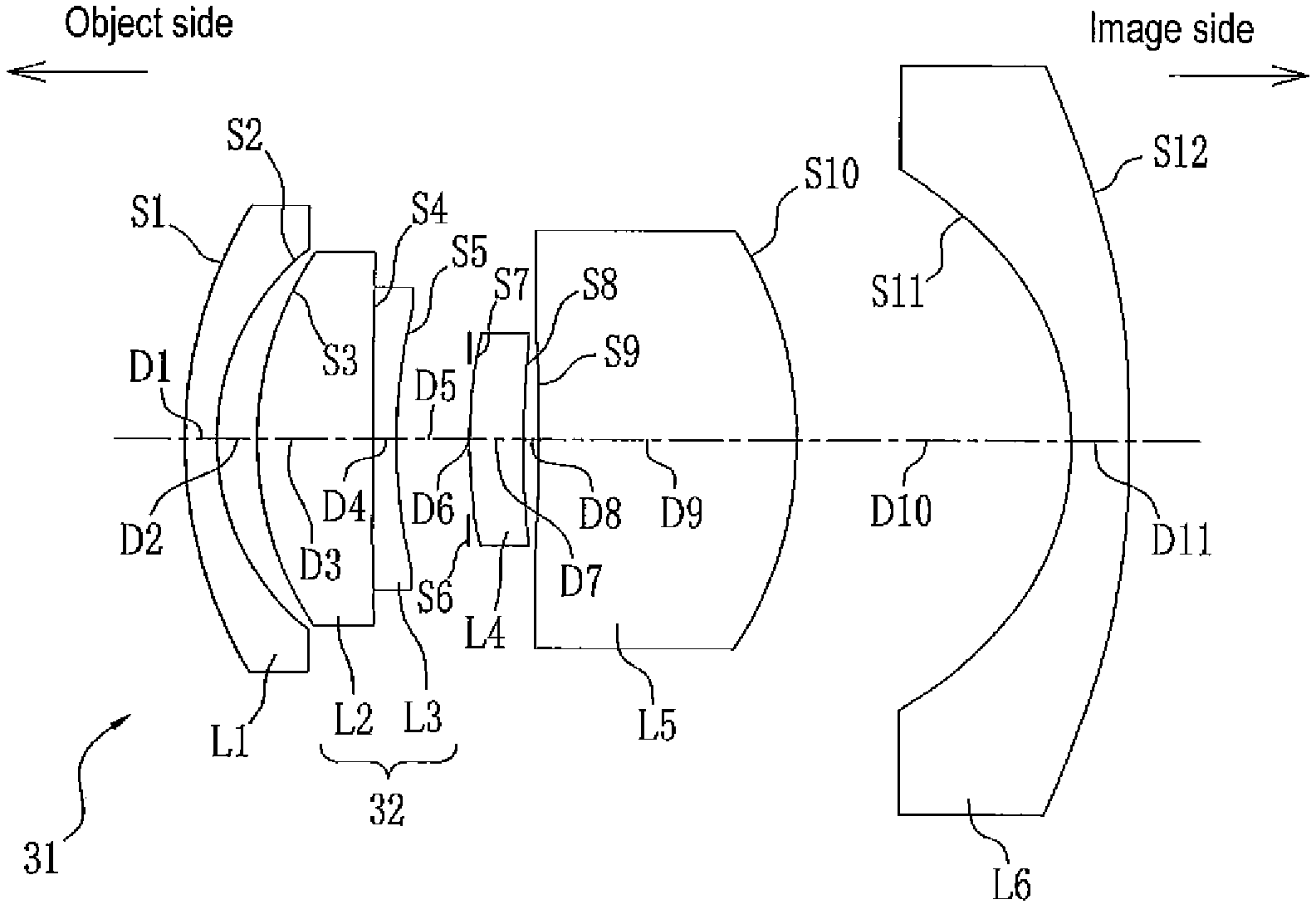
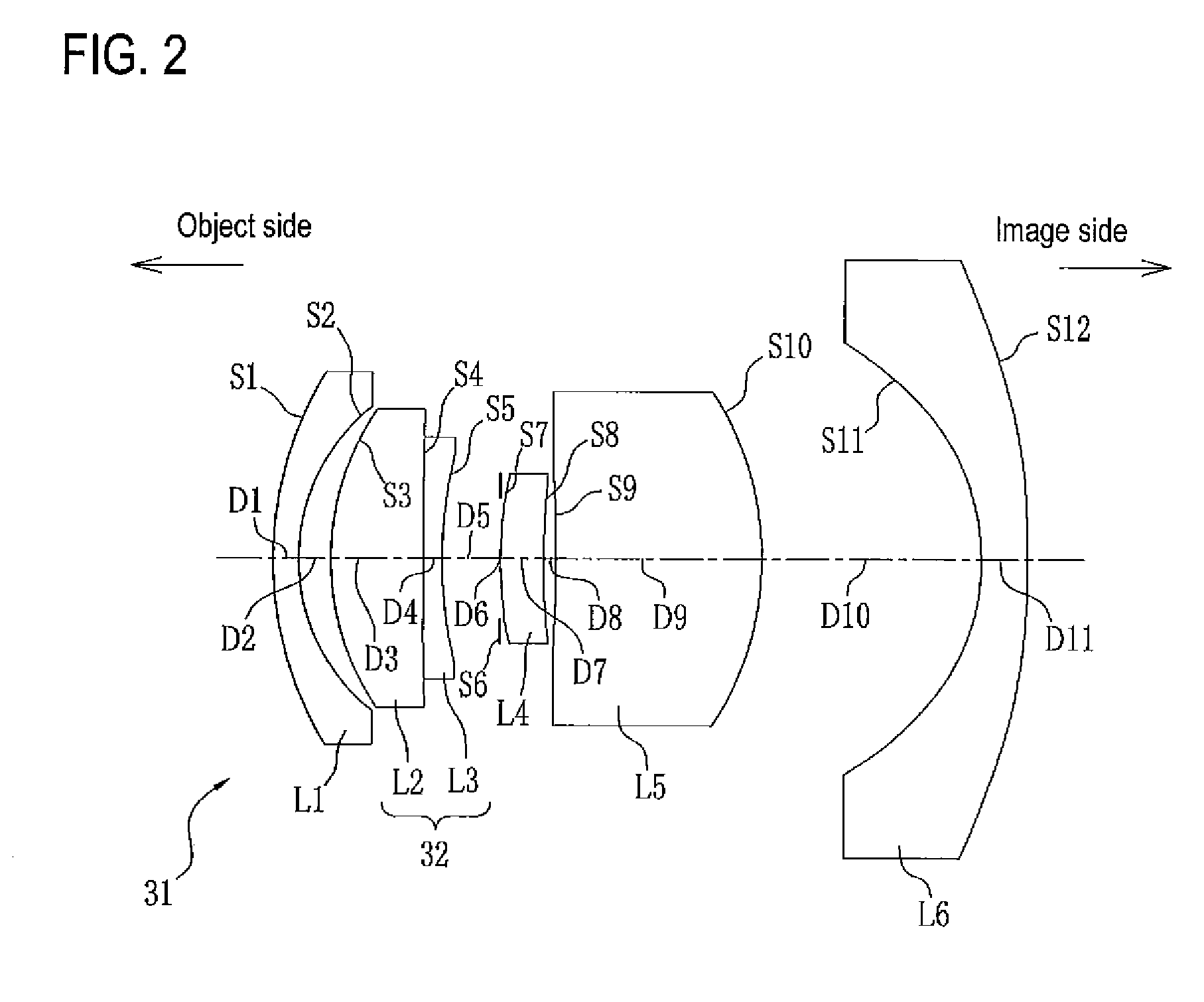
[0070]As shown in FIG. 2, an image reading lens system 31 according to Example 1 includes six lenses having first to sixth lenses L1 to L6 that are arranged in order from the object side and an aperture diaphragm S6. The aperture diaphragm S6 is disposed between the third lens L3 and the fourth lens L4. Specifically, in the image reading lens system 31, there are arranged, in order from the object side, a front group (the first lens L1, the second lens L2, and the third lens L3), the aperture diaphragm S6, and a rear group (the fourth lens L4, the fifth lens L5, and the sixth lens L6). In addition, the second lens L2 and the third lens L3 form a cemented lens 32.

[0071]In the image reading lens system 31, the first lens L1, the third lens L3, and the sixth lens L6 are formed of negative lenses, and the second lens L2, the fourth lens L4, and the fifth lens L5 are formed of positive lenses.

[0072]As lens data of the image reading lens system 31, Table 1 shows a radius of curvature Ri (...

example 2

[0088]As shown in FIG. 5, an image reading lens system 36 according to Example 2 includes six lenses having first to sixth lenses L1 to L6 that are arranged in order from the object side and an aperture diaphragm S6. The aperture diaphragm S6 is disposed between the third lens L3 and the fourth lens L4. Specifically, in the image reading lens system 36, there are arranged, in order from the object side, a front group (the first lens L1, the second lens L2, and the third lens L3), the aperture diaphragm S6, and a rear group (the fourth lens L4, the fifth lens L5, and the sixth lens L6). In addition, the second lens L2 and the third lens L3 form a cemented lens 37.

[0089]In the image reading lens system 36, the first lens L1, the third lens L3, and the sixth lens L6 are formed of negative lenses, and the second lens L2, the fourth lens L4, and the fifth lens L5 are formed of positive lenses.

TABLE 4SiRiDiNdjνdj(Surface(Radius of(Surface(Refractive(Abbenumber)curvature)spacing)index)numb...

example 3

[0101]As shown in FIG. 8, an image reading lens system 41 according to Example 3 includes six lenses having first to sixth lenses L1 to L6 that are arranged in order from the object side and an aperture diaphragm S6. The aperture diaphragm S6 is disposed between the third lens L3 and the fourth lens L4. Specifically, in the image reading lens system 41, there are arranged, in order from the object side, a front group (the first lens L1, the second lens L2, and the third lens L3), the aperture diaphragm S6, and a rear group (the fourth lens L4, the fifth lens L5, and the sixth lens L6). In addition, the second lens L2 and the third lens L3 form a cemented lens 42.

[0102]In the image reading lens system 41, the first lens L1, the third lens L3, and the sixth lens L6 are formed of negative lenses, and the second lens L2, the fourth lens L4, and the fifth lens L5 are formed of positive lenses.

TABLE 7SiRiDiNdjνdj(Surface(Radius of(Surface(Refractive(Abbenumber)curvature)spacing)index)numb...


PUM


Abstract

An image reading lens system of Example 1 includes six lenses having first to sixth lenses being arranged in order from an object side and an aperture diaphragm. In the image reading lens system, the first lens, the third lens, and the sixth lens are formed of negative lenses, and the second lens, the fourth lens, and the fifth lens are formed of positive lenses. The first lens, the second lens, the third lens, and the fifth lens are made of glass, and surfaces of all these lenses are formed of spherical surfaces. The fourth lens and the sixth lens are made of resin, and surfaces of the fourth lens and surfaces of the sixth lens are formed of aspheric surfaces. A cemented lens is formed of the second lens and the third lens with a cemented surface interposed therebetween, and is disposed adjacent to the aperture diaphragm.

Description

CROSS-REFERENCE TO RELATED APPLICATIONS[0001]This application is based upon and claims the benefit of priority from the Japanese Patent Application No.2008-48605 filed on Feb. 28, 2008; the entire contents of which are incorporated herein by reference.BACKGROUND OF THE INVENTION[0002]1. Technical Field[0003]The invention relates to an image reading apparatus such as an image scanner and an image reading lens system mounted on the image reading apparatus.[0004]2. Description of the Related Art[0005]Recently, image reading apparatuses for scanning an original such as a document or an image and reading the original as digital image data has come into widespread use. Known image reading apparatuses include a copier, a facsimile, an image scanner, and a multi-function device having these functions and the like. These image reading apparatuses irradiate light onto an original placed on a given position to form an image of the original on a solid-state imaging device such as CCD by using l...

Claims


Application Information

Patent Timeline
IPC IPC(8): G02B13/18
CPCG02B7/008G02B13/06G02B9/62
Inventor YAMAMOTO, YOKO
Owner FUJI PHOTO OPTICAL CO LTD
Features
  • Generate Ideas
  • Intellectual Property
  • Life Sciences
  • Materials
  • Tech Scout
  • Unparalleled Data Quality
  • Higher Quality Content
  • 60% Fewer Hallucinations
Learn More