
Imaging device

a technology of imaging device and control circuit, which is applied in the direction of mountings, instruments, television systems, etc., can solve the problems of short circuit, damage, and deterioration of adhesives, and achieve the effect of preventing infiltration of foreign matter and suppressing focus movemen

Active Publication Date: 2016-04-07
FUJIFILM CORP +1
View PDF4 Cites 18 Cited by
  • Summary
  • Abstract
  • Description
  • Claims
  • Application Information

AI Technical Summary

Benefits of technology

This patent is about an imaging device that prevents water or other foreign matter from getting inside the camera. This is important because when the camera is installed inside a car, it can get dirty. The imaging device uses a double structure to hold the camera's lens, which prevents movement caused by temperature changes and prevents liquid or dust from getting inside. This makes the camera more reliable and durable.

Problems solved by technology

This is because in many cases, an imaging device which is used in a harsh environment is exposed to liquid, dust, or the like as well as a temperature variation and thus if foreign matter such as liquid or dust infiltrates, there is a possibility that a photographed image may deteriorate due to dew condensation or dirt or a control circuit of an imaging element may be short-circuited and damaged.
However, the barrel base portion or the lens support portion repeatedly expand and contract due to a temperature variation, and thus an adhesive deteriorates, whereby there is a case where the infiltration of foreign matter such as liquid or dust becomes easy.
However, if these cylinders repeatedly expand and contract due to a temperature variation, there is a possibility that foreign matter such as liquid or dust may infiltrate from the gap between these cylinders.
Similarly, in the imaging device disclosed in JP2008-211780A, when changing the mounting position of the lens holding unit, there is a possibility that foreign matter such as liquid or dust may infiltrate from the gap between the intermediate member and the lens holding unit.

Method used


Image

  • Imaging device
  • Imaging device
  • Imaging device

Examples


Embodiment Construction

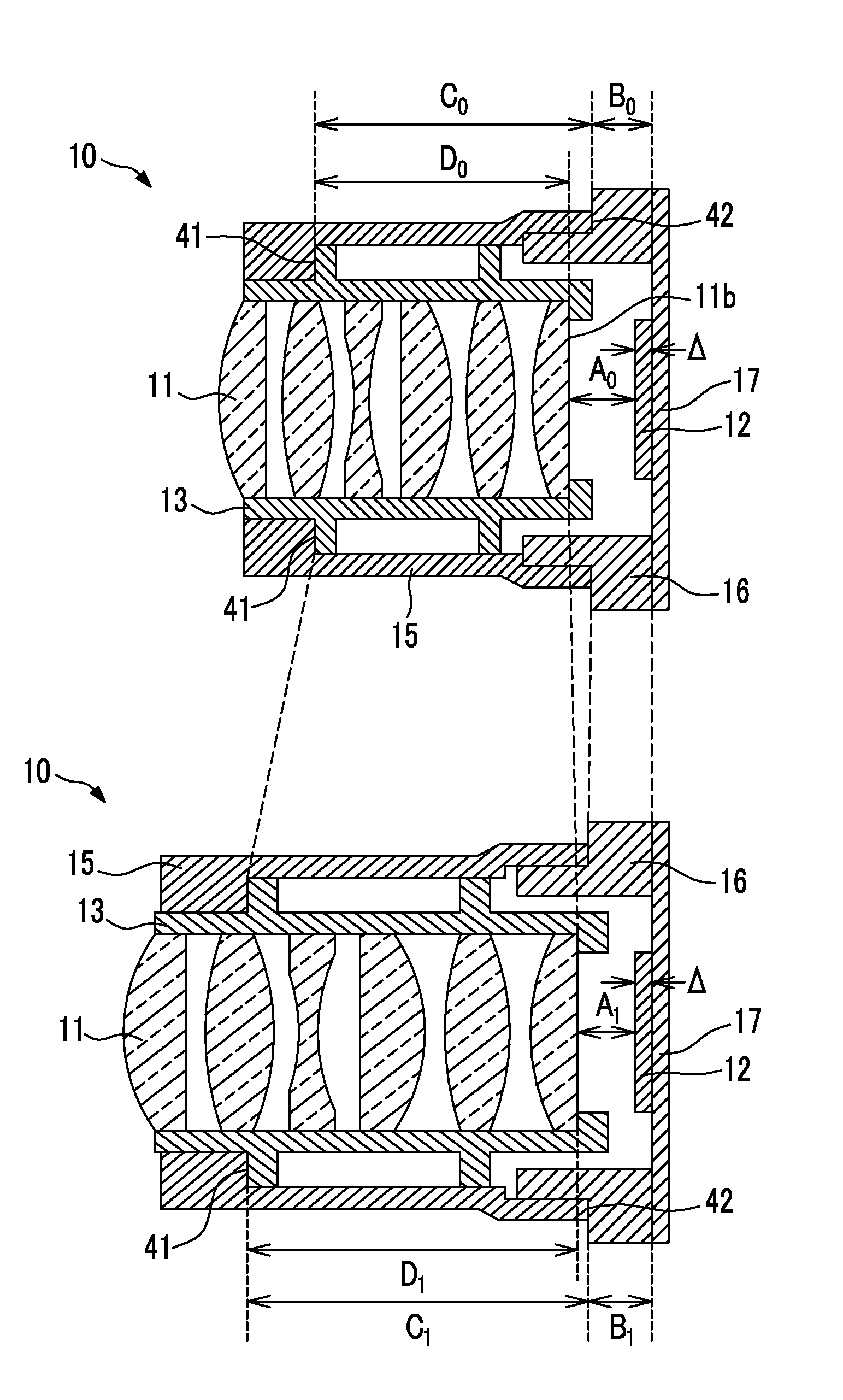
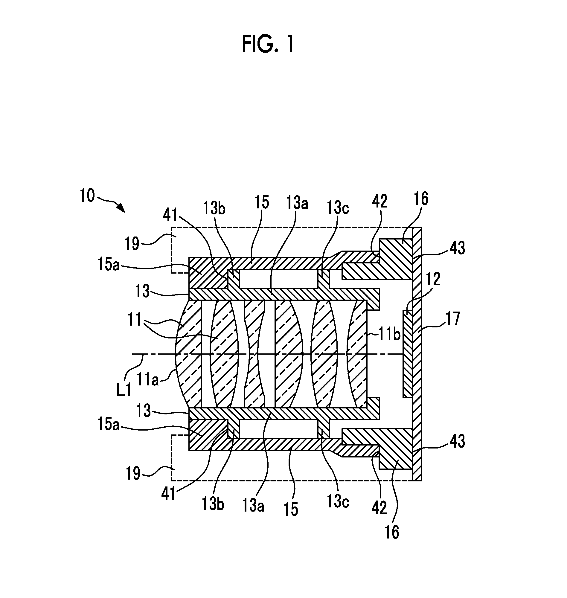
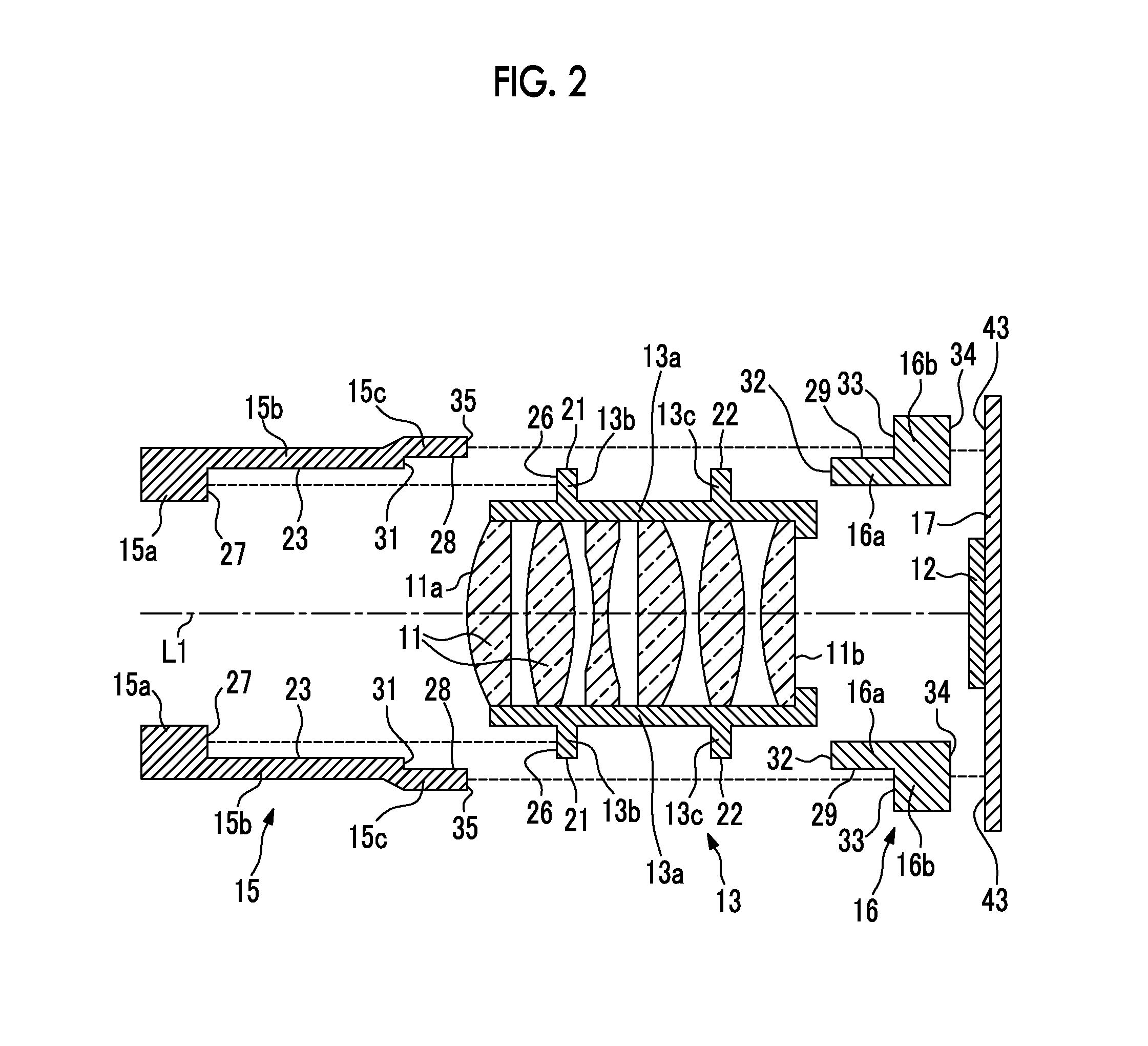
[0033]As shown in FIGS. 1 and 2, an imaging device 10 is provided with an imaging lens 11 and an imaging element 12 and captures an image of a photographic subject which is formed by the imaging lens 11, by the imaging element 12. The imaging device 10 is, for example, a car-mounted camera which is installed in the interior of an automobile.

[0034]The imaging lens 11 is a fixed focus lens, is configured with, for example, a lens, a mirror, a prism, or the like, and includes a member which does not substantially have power, such as an optical filter, as necessary. An optical axis L1 of the imaging lens 11 is also the central axes of a lens barrel 13 and an intermediate member 15. In FIG. 1, an imaging lens 11 composed of six lenses is shown as an example. However, the thickness or the surface shape of each lens, the number of lenses, or the presence or absence of other members is selectable. Further, all of the respective lenses configuring the imaging lens 11 are, for example, glass ...


PUM


Abstract

The present invention provides an imaging device in which focus movement due to a temperature variation is suppressed and the infiltration of foreign matter such as liquid or dust is prevented. An imaging device 10 is provided with an imaging lens 11, an imaging element 12, and an intermediate member 15. The imaging lens 11 is held by a lens-barrel 13 and forms an image of a photographic subject. The imaging element 12 captures the image of the photographic subject which is formed by the imaging lens 11. The intermediate member 15 has, on the inner-peripheral-surface of one end thereof, a flange portion 15a which comes into contact with the lens-barrel 13, and holds the lens-barrel 13 by joining the front surface 26 of a flange portion 13b of the lens-barrel 13 and the surface 27 on the imaging element 12 side of the flange portion 15a to each other.

Description

CROSS-REFERENCE TO RELATED APPLICATIONS[0001]This application is a Continuation of PCT International Application No. PCT / JP2014 / 058293 filed on Mar. 25, 2014, which claims priority under 35 U.S.C §119(a) to Japanese Patent Application No. 2013-081645 filed on Apr. 9, 2013. Each of the above application(s) is hereby expressly incorporated by reference, in its entirety, into the present application.BACKGROUND OF THE INVENTION[0002]1. Field of the Invention[0003]The present invention relates to an imaging device which captures an image of a photographic subject which is formed by an imaging optical system such as a lens, by an imaging element, and an imaging device which is used in an environment in which a temperature variation is large.[0004]2. Description of the Related Art[0005]An imaging device which captures an image of a photographic subject which is formed by an imaging optical system such as a lens, by an imaging element, has become popularized. The imaging device is used in e...

Claims


Application Information

Patent Timeline
Patent Type & Authority Applications(United States)
IPC IPC(8): G02B7/02H04N5/225
CPCG02B7/028H04N5/2254G02B7/025H04N23/55
Inventor KOBORI, MAKOTOISHII, YOSHIAKISASAKI, NAOKI
Owner FUJIFILM CORP
Features
  • Generate Ideas
  • Intellectual Property
  • Life Sciences
  • Materials
  • Tech Scout
  • Unparalleled Data Quality
  • Higher Quality Content
  • 60% Fewer Hallucinations
Learn More