Athletic Shoe Cleat With Dynamic Traction and Method of Making and Using Same

Active Publication Date: 2009-09-10
SOFTSPIKES
View PDF21 Cites 70 Cited by
  • Summary
  • Abstract
  • Description
  • Claims
  • Application Information

AI Technical Summary

Benefits of technology

[0010]It is an object of the present invention to provide a cleat structure, and a shoe and cleat combination, in which dynamic traction elements on the cleat can b

Problems solved by technology

However, the method of separately molding the dynamic elements unit and then attaching that unit to the hub by means of a separate connector is costly and results in the possibility of the traction element unit body becoming detache

Method used


Image

  • Athletic Shoe Cleat With Dynamic Traction and Method of Making and Using Same
  • Athletic Shoe Cleat With Dynamic Traction and Method of Making and Using Same
  • Athletic Shoe Cleat With Dynamic Traction and Method of Making and Using Same

Examples


Embodiment Construction

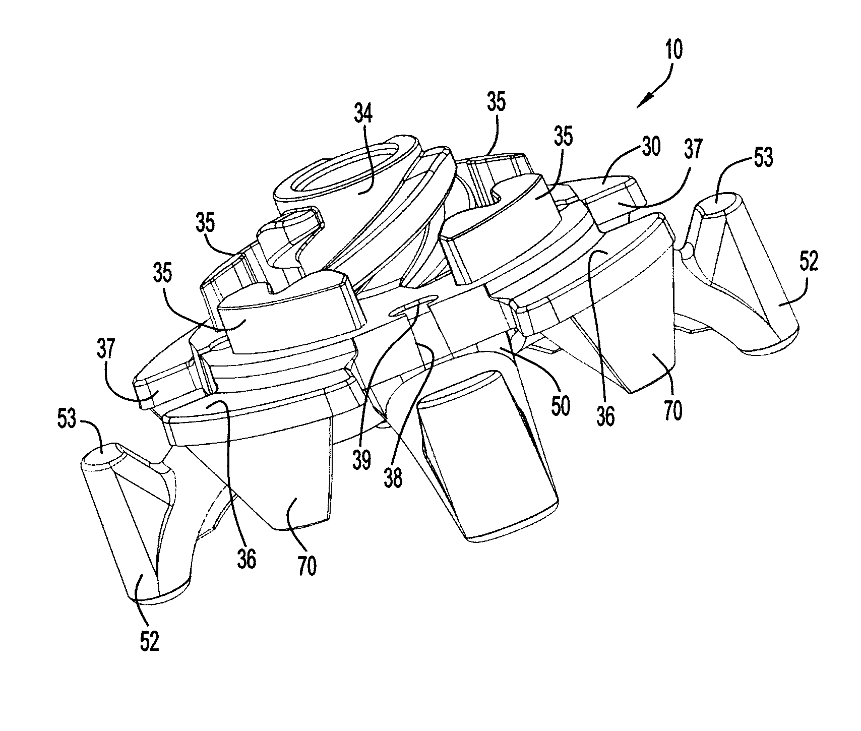
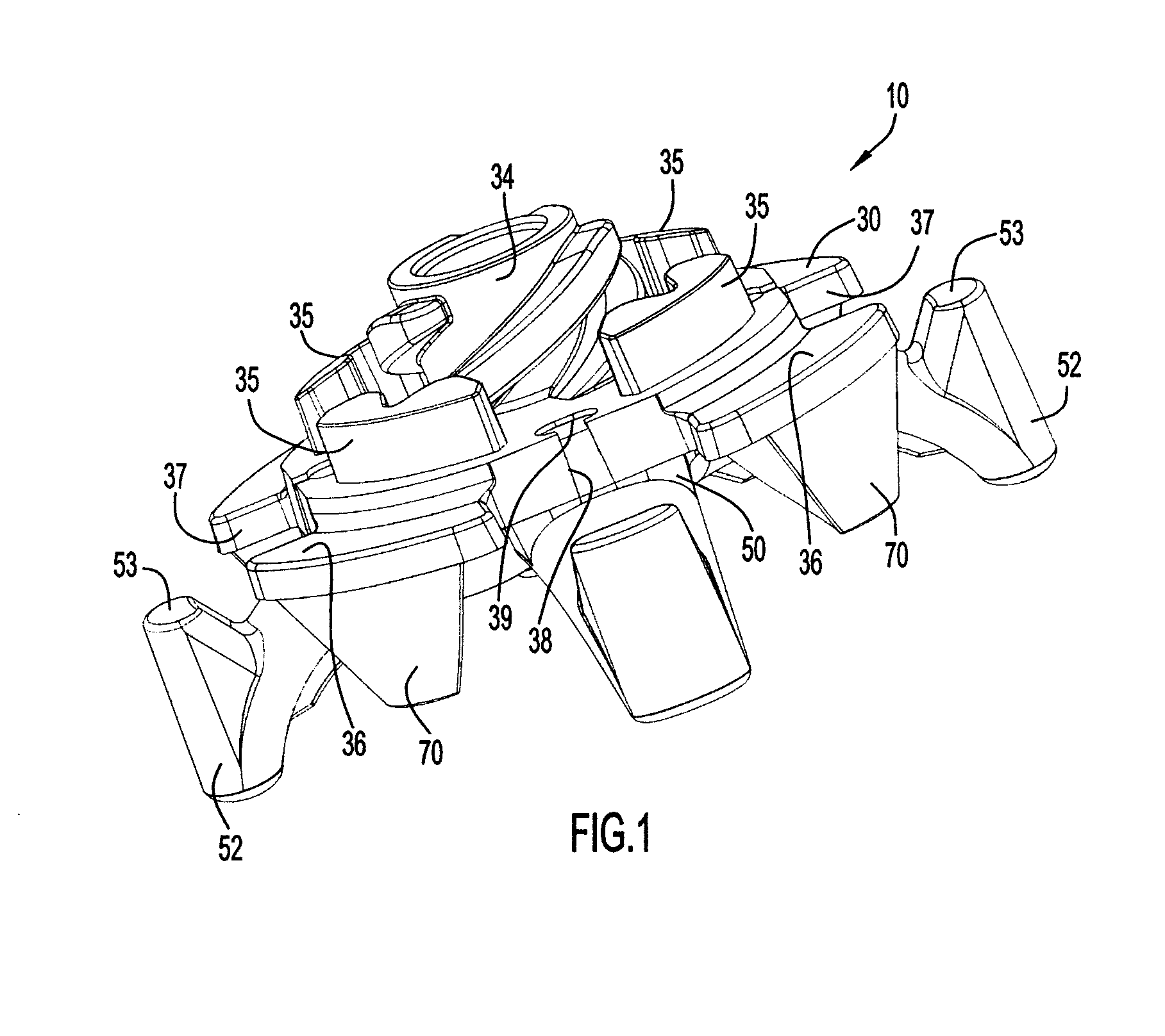
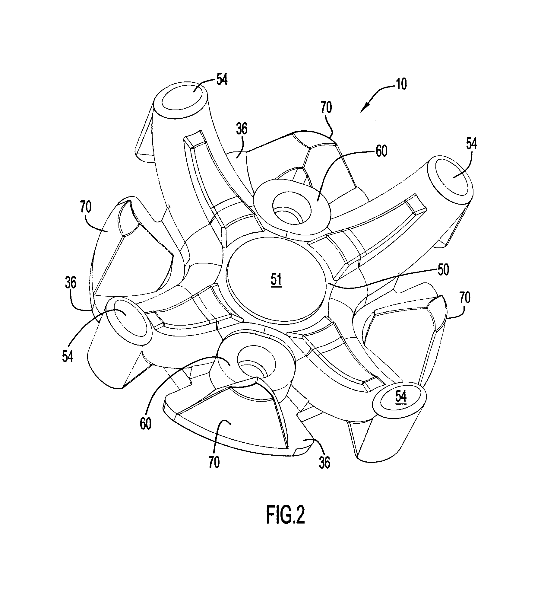
[0036]The following detailed description of FIGS. 1-12 and of the preferred embodiments reveal the methods and apparatus of the present invention. It is to be understood that the relative directional terms “top”, “bottom”, “upward”, downward”, “vertical” and horizontal”, and the like, as used herein, refer to the orientation in a shoe outsole in which the cleat of the invention is installed when the shoe outsole rests on or is forced against a horizontal surface such as the ground, and these terms are not limiting on the orientation of the cleat or the scope of the invention. For purposes of understanding, the following directional terms as used herein shall have the following meanings: “angular” means the rotational direction about the central longitudinal axis A-A of the cleat about which the cleat is rotated during installation in a receptacle in the shoe outsole; “radial” refers to the direction perpendicular to axis A-A; and “axial” refers to the direction along or parallel to ...


PUM


Abstract

A single component traction cleat of co-molded hub and dynamic traction portions includes dynamic traction elements flexible about proximal ends secured inboard of and below a hub periphery having cut-outs through which the elements move when flexed. The hub has a cross-like configuration with spoke-like legs from which static traction elements depend. Locking posts located on the hub spoke legs include a recess between two symmetrical interference sections for receiving a locking tooth on a mating receptacle.

Description

CROSS REFERENCE TO RELATED APPLICATION[0001]This application claims priority from U.S. Provisional Patent Application Ser. No. 61 / 034,204 entitled “Improved Athletic Shoe Cleat With Dynamic Traction,” filed Mar. 6, 2008. The disclosure of this provisional patent application is incorporated herein by reference in its entirety.BACKGROUND OF THE INVENTION[0002]1. Technical Field[0003]The present invention pertains to athletic shoes, particularly golf shoes, and to improved traction cleats removably connected to the outsole of such shoes. The invention further pertains to improved methods of fabricating the cleats, installing the cleats on shoe outsoles, and the operation of the cleats to provide traction.[0004]2. Discussion of the Prior Art[0005]It is known in the prior art to provide replaceable plastic cleats for athletic shoes utilizing dynamic traction elements that are secured to and project downwardly and outwardly from a hub and resiliently flex under the load of the weight of a...

Claims


Application Information

Patent Timeline
IPC IPC(8): A43B5/00A43C15/02
CPCA43C15/161A43C15/06A43C15/00
Inventor KRIKORIAN, RAND J.BURT, JOHN ROBERT
Owner SOFTSPIKES
Why Eureka
Try Eureka