Roof tile or tiled solar thermal collector

Inactive Publication Date: 2009-09-10
GENERAL ELECTRIC CO
View PDF4 Cites 48 Cited by
  • Summary
  • Abstract
  • Description
  • Claims
  • Application Information

AI Technical Summary

Problems solved by technology

Typically, however, solar collectors are mount

Method used


Image

  • Roof tile or tiled solar thermal collector
  • Roof tile or tiled solar thermal collector
  • Roof tile or tiled solar thermal collector

Examples


Embodiment Construction

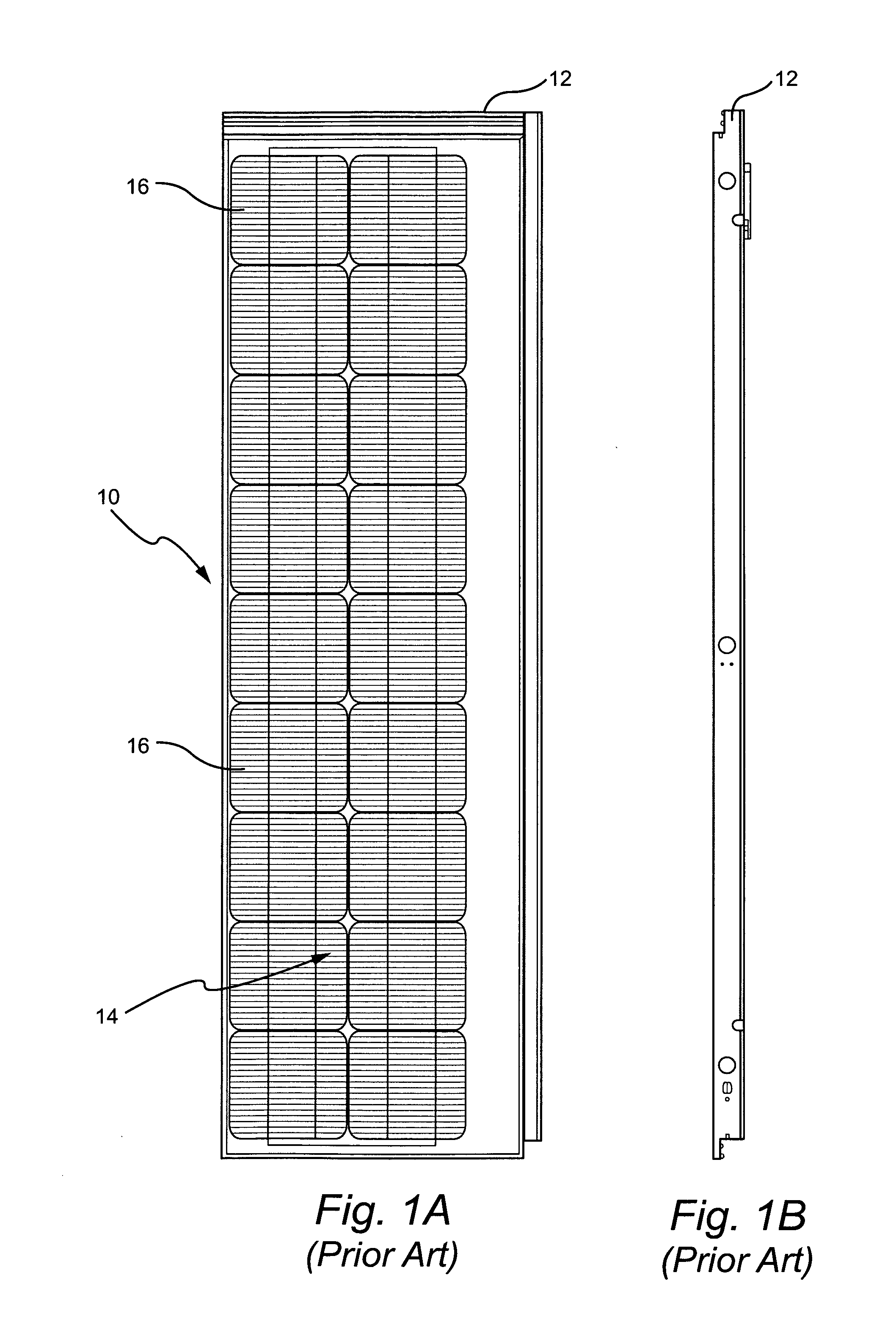
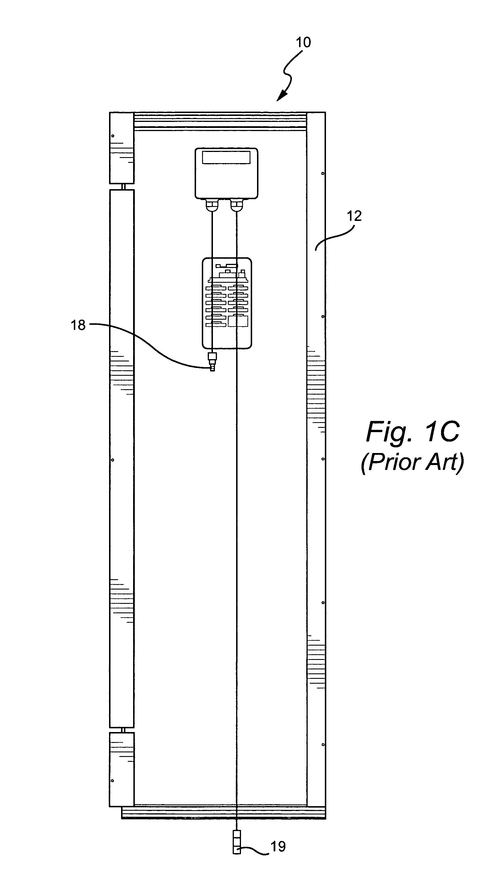
[0017]FIGS. 1A, 1B and 1C are top, side and bottom views, respectively, of a photovoltaic solar module 10 that is designed to generate between 50-90 watts of power. The module 10 is a building integrated module, in that it is designed to look like common concrete roof tiles so that it blends discretely into a roof on which it is placed. The module 10 includes a frame 12 of a specified length, width and depth designed to conform the module 10 to the size of a standard concrete roof tile. Mounted within the frame 12 is an array 14 of single-crystal cells 16 connected in series to produce a specified amount of power generated by module 10. Preferably, there are 18 cells 16 comprising array 14 that produce between 50-90 watts of power. Connecting the array 14 of cell 16 to other modules 10 and / or equipment using the power generated by module 10 are a positive lead 18 and a negative lead 19 shown in FIG. 1C.

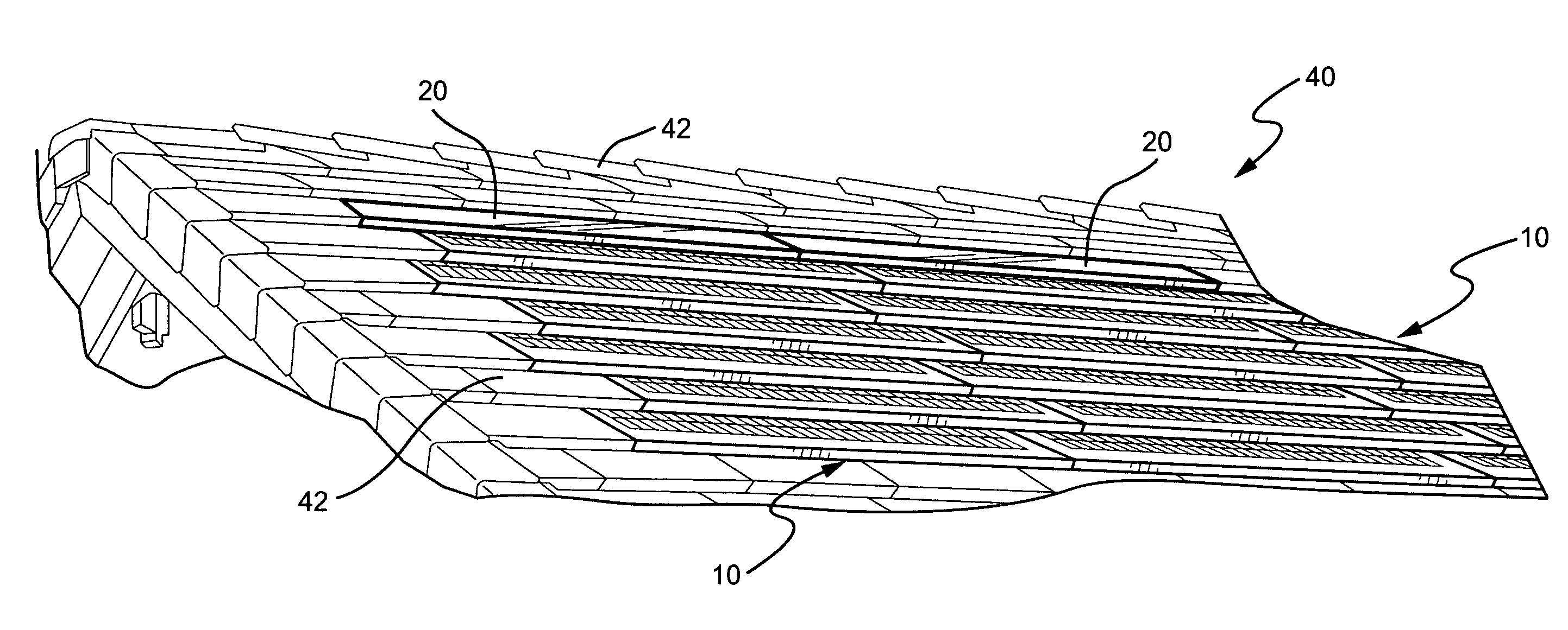
[0018]FIGS. 2A and 2B are top and side views, respectively, of a solar thermal co...


PUM


Abstract

A building roof tile system and integrated solar energy system is disclosed that includes a solar thermal collector which is intended to replace a standard flat concrete roof tile or an S-tile type clay roof tile so as to be integrated with the concrete tiles and photovoltaic (“PV”) solar panels that are also designed to look like common concrete roof tiles. The solar thermal collector includes mounting components that allow the collector to be mounted in a manner similar to that of the concrete and PV roof tiles, so as to be discretely integrated with the other roof tiles.

Description

[0001]The present invention is directed to solar panels for roofs, and more particularly, to a building roof tile system and integrated solar energy system that includes a thermal solar collector which is designed to replace standard flat cement roof tiles or S-tile type roof tiles.BACKGROUND OF THE INVENTION[0002]Solar thermal systems collect heat from the sun and use it to heat space or water. Solar thermal systems include components that collect the solar heat, store the heat, and deliver the heat to where it is needed.[0003]Solar collectors are the components of solar thermal systems that collect solar heat. Typically, they sit on the roof of a house, where they are readily visible. There are several different types of solar collectors.[0004]The most common type of solar collector is the glazed flat plate collector. This type of collector includes a weatherproofed, insulated box or frame containing a metal absorber plate with built-in pipes. Typically, it is two to three inches ...

Claims


Application Information

Patent Timeline
IPC IPC(8): H01L31/042F24J2/04E04D13/18F24S10/40
CPCF24J2/0455F24J2002/0092Y02B10/12H02S20/25Y02B10/22Y02E10/44Y02B10/20F24S2020/17F24S20/69Y02E10/50Y02B10/10Y02E10/40
Inventor CURTIN, GERALDRESSLER, STEPHEN
Owner GENERAL ELECTRIC CO
Why Eureka
Try Eureka