Spirally Wound Electrical Cable for Enhanced Magnetic Field Cancellation and Controlled Impedance

a magnetic field cancellation and spiral wound technology, applied in the direction of power cables, cables, insulated conductors, etc., can solve the problems of uneven or precisely twisted wires, uncontrollable impedance cancellation of magnetic fields, and inability to uniformly or precisely twist the two wires in the twisted pair cable throughout the cable, so as to achieve uniform winding rate of wires and control of impedance between signal conductor wires

Inactive Publication Date: 2009-09-10
IBM CORP
View PDF16 Cites 3 Cited by
  • Summary
  • Abstract
  • Description
  • Claims
  • Application Information

AI Technical Summary

Benefits of technology

[0013]Impedances between the signal conductor wires are controllable by setting spacing between the signal wires, spacing of the signal wires from the central conductor core, and dielectric...

Problems solved by technology

However, it is difficult to twist the two wires in the twisted pair cable uniformly or precisely throughout the cable.
However, the twisted pair cable includes individual loosely paired wires that are hard to wind uniformly.
Due to the non-uniform winding of the two wires, the distance between the two wires may not be identical along the twisted pair cable.
Further, due to the non-uniform twisting of the two ...

Method used


Image

  • Spirally Wound Electrical Cable for Enhanced Magnetic Field Cancellation and Controlled Impedance
  • Spirally Wound Electrical Cable for Enhanced Magnetic Field Cancellation and Controlled Impedance
  • Spirally Wound Electrical Cable for Enhanced Magnetic Field Cancellation and Controlled Impedance

Examples


Embodiment Construction

[0021]The invention will now be described in more detail by way of example with reference to the embodiments shown in the accompanying figures. It should be kept in mind that the following described embodiments are only presented by way of example and should not be construed as limiting the inventive concept to any particular physical configuration.

[0022]Further, if used and unless otherwise stated, the terms “upper”, “lower”, “front”, “back”, “over”, “under”, and similar such terms are not to be construed as limiting the invention to a particular orientation. Instead, these terms are used only on a relative basis.

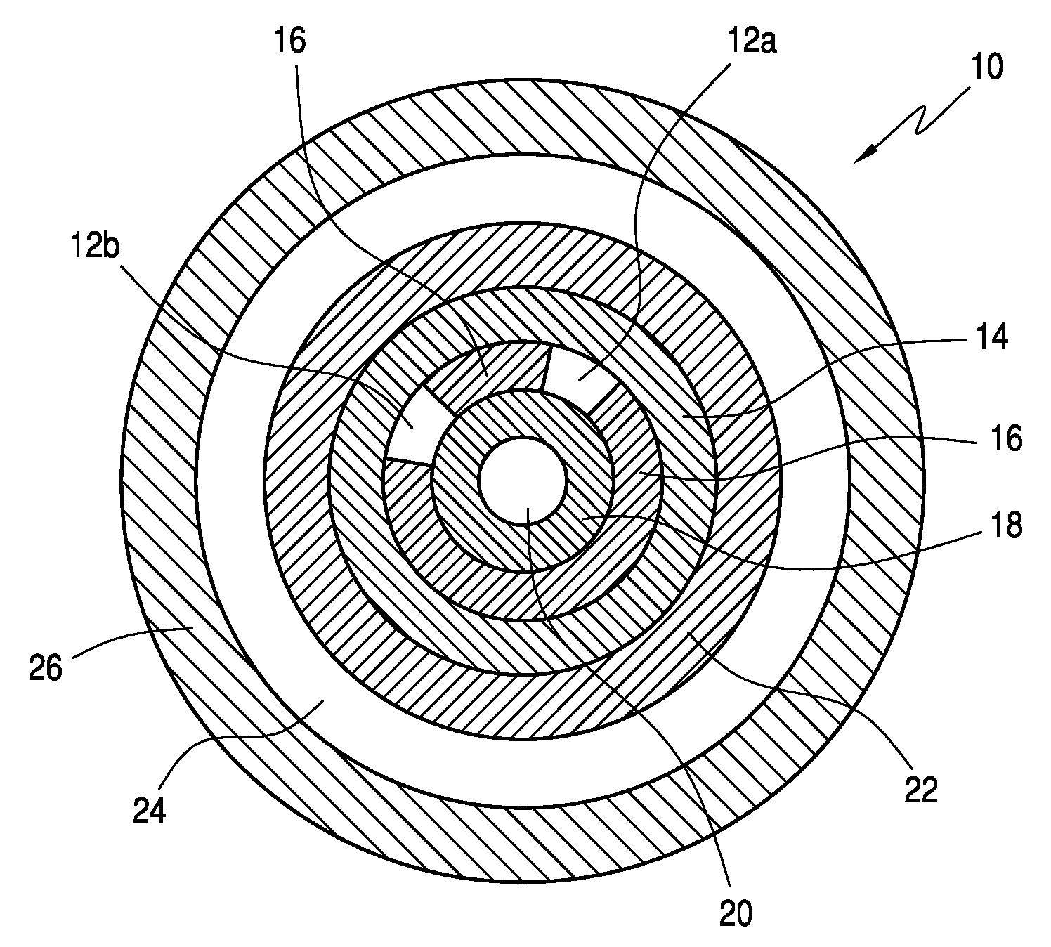
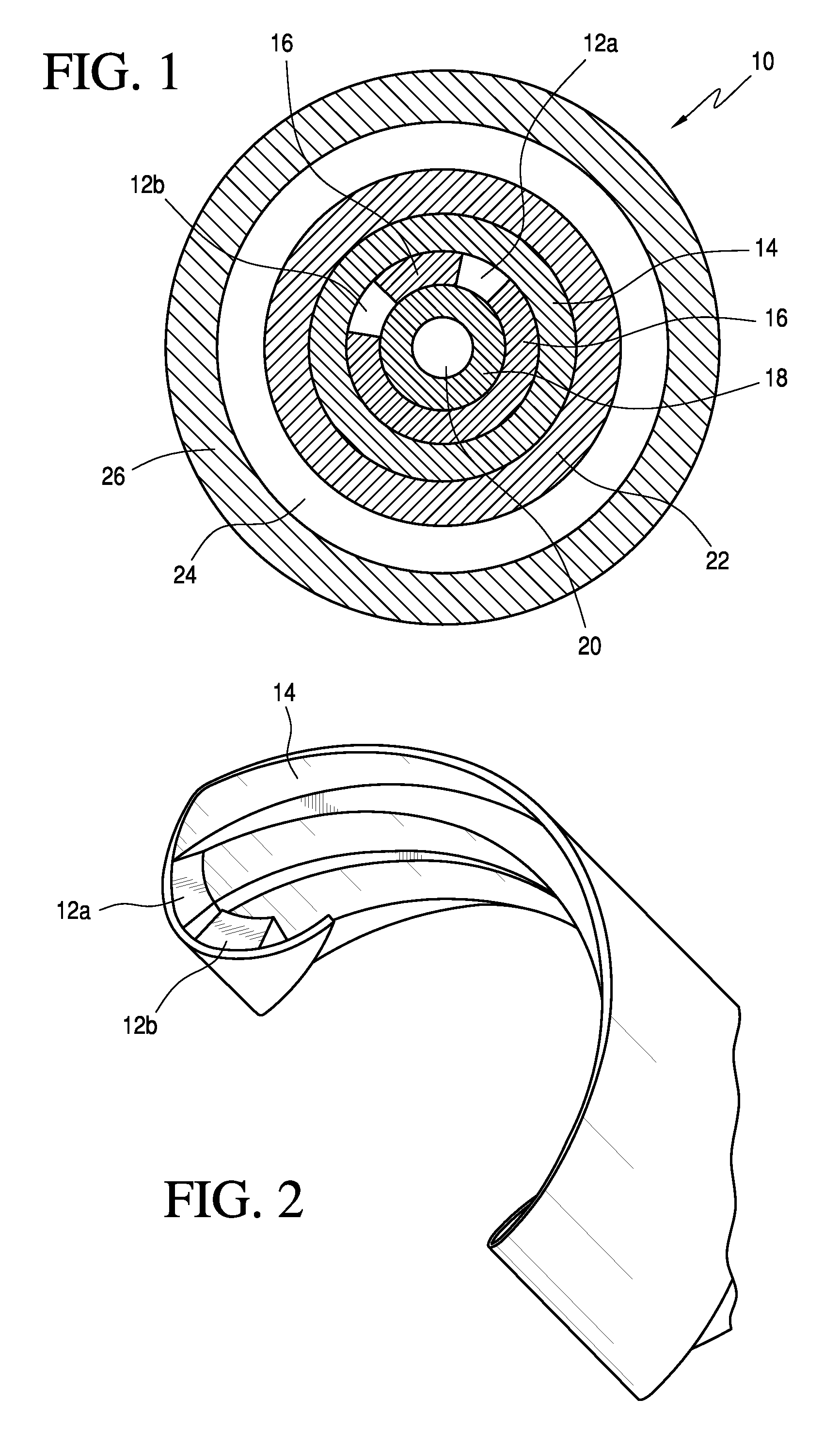
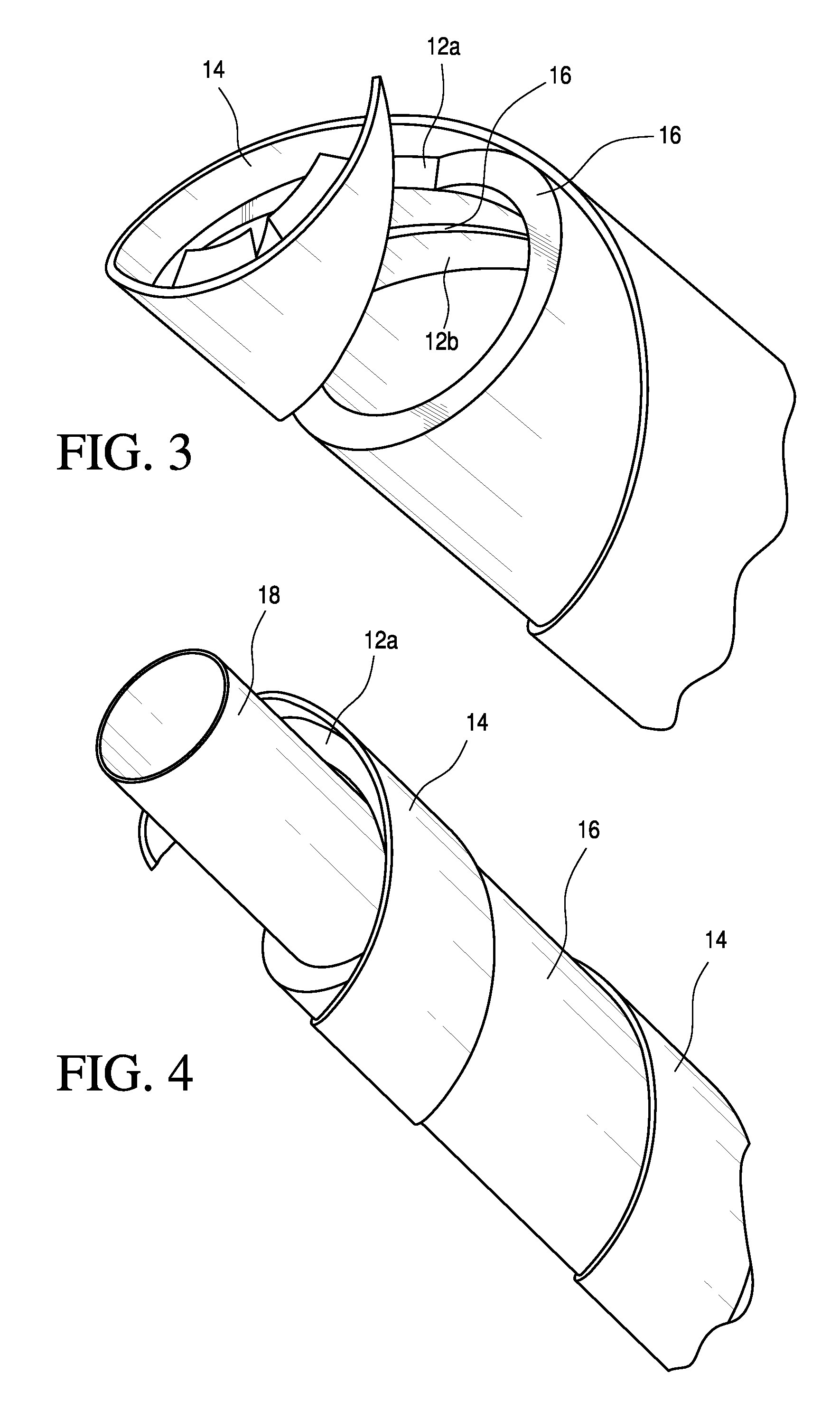
[0023]FIG. 1 is a cross-sectional view of a spirally wound cable 10, according to an exemplary embodiment of the present invention. The cable 10 includes a pair of signal conductor wires 12a and 12b, a first dielectric layer 14, a second dielectric layer 16, a third dielectric layer 18, a central conductor core 20, a fourth dielectric layer 22, a shield layer 24 and an out...


PUM


Abstract

An electrical cable with enhanced magnetic fields and better controlling of impedances. The electrical cable includes a central ground core, an inner dielectric layer surrounding the central ground core, and a pair of signal conductor wires spirally wound on the inner dielectric layer. The signal conductor wires are separated from the central ground core by a thickness of the inner dielectric layer, and spaced apart from each other and parallel to each other. The cable further includes an intermediate dielectric layer disposed between the signal conductor wires and an outer dielectric layer surrounding the signal conductor wires and the intermediate dielectric layer.

Description

BACKGROUND OF THE INVENTION[0001]1. Field of the Invention[0002]The invention relates to an electrical cable, and in particular, to a spirally wound cable that enhances the cancellation of magnetic fields and better controls differential mode impedance and common mode impedance.[0003]2. Background Information[0004]Twisted pair cable is a form of wiring in which two signal conductor wires are wound together for the purpose of canceling out electromagnetic interference (EMI) from external sources, electromagnetic radiation from the cable, and / or crosstalk between signal conductor pairs. The typical twisted pair cable operates in a differential mode where the two wires carry equal and opposite signals, and in a common mode where the two wires carry equal signals in the same direction.[0005]The twisted pair cable generates magnetic fields around each of the two conductor wires. So as to produce equal and opposite magnetic fields that cancel each other out, the two wires should be unifor...

Claims


Application Information

Patent Timeline
IPC IPC(8): H01B11/02H01B7/18
CPCH01B7/0018H01B11/00H01B7/0241H01B7/0225
Inventor GILLILAND, DON A.WURTH, DENNIS J.
Owner IBM CORP
Why Eureka
Try Eureka