Modular LED Lighting Fixtures

a technology of led lighting fixtures and modules, applied in the field of lighting technology, can solve the problems of low efficiency of incandescent lighting and the expected increase in electricity cost in the future, and achieve the effects of convenient installation, convenient low cost and convenient installation

Active Publication Date: 2009-09-10
KORRUS INC
View PDF14 Cites 50 Cited by
  • Summary
  • Abstract
  • Description
  • Claims
  • Application Information

AI Technical Summary

Benefits of technology

[0006]Embodiments hereafter disclosed provide a set of interconnected, modular LED lighting fixture components that can be arranged and easily installed in the field in a wide variety of forms and shapes to meet the needs of designers and architects. Various embodiments facilitate low cost, yet attractive designs using LED lighting fixtures suitable, for example, for cove lighting applications and readily installed in the field due to various features. One such feature is a field-installable unitary cover member having a circuit board mounting platform integrally formed with suitable heat sinking and which mounts onto a cooperating base chassis. In one embodiment, the circuit board mounting platform extends farther from one end of the cover member than the other so as to facilitate placement of LEDs in a fashion to maintain relatively uniform spacing of the LED lamps, thereby enhancing lighting uniformity and minimizing dark spots. Various combinations and adaptations of such features in various embodiments facilitate practical use of energy efficient, high power LED lighting technology at modest cost in attractive and easily field installed configurations for architects and designers.

Problems solved by technology

Incandescent lighting has a low efficiency since much of the electrical power supplied to such lighting is converted to heat instead of light.
The cost of electricity is expected to increase in the future as the cost of producing electricity rises.

Method used


Image

  • Modular LED Lighting Fixtures
  • Modular LED Lighting Fixtures
  • Modular LED Lighting Fixtures

Examples


Embodiment Construction

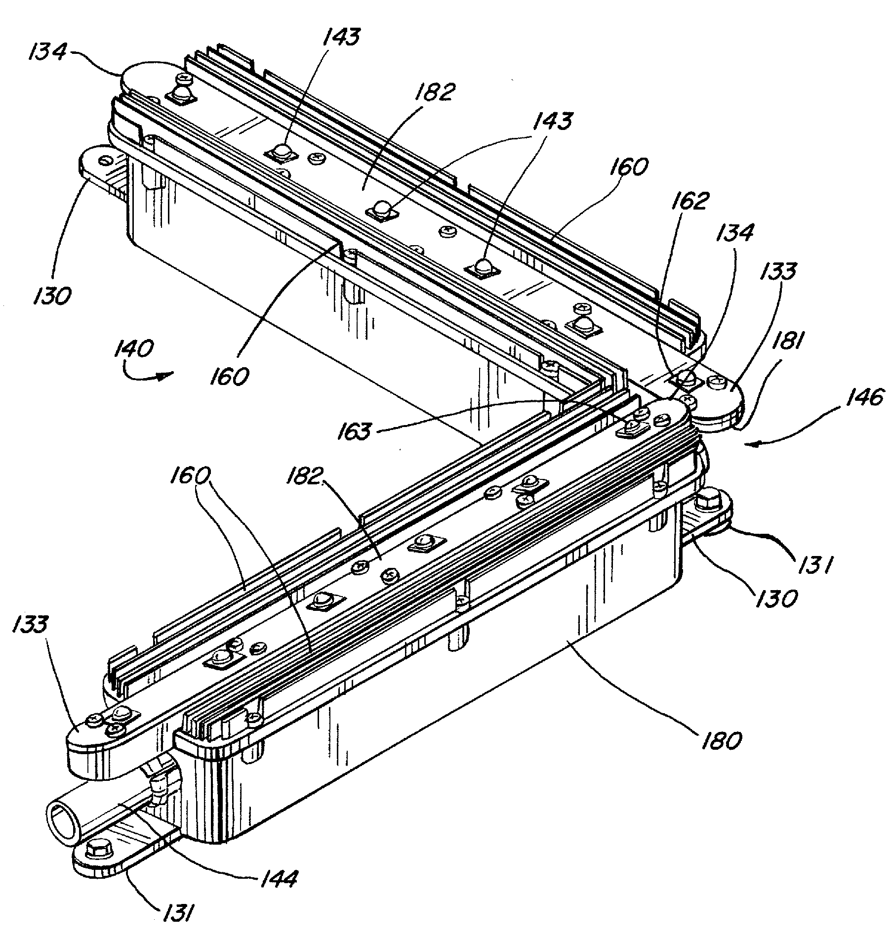
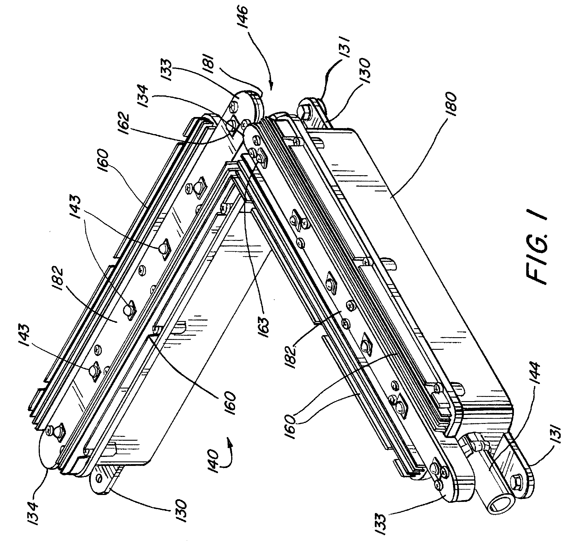
[0022]Further features and advantages, as well as the structure and operation of various embodiments are described in detail below with reference to the accompanying FIGS. 1-8, wherein like reference numerals refer to like elements. The embodiments are described in the context of several component designs with compatible electrical connectors and localized heat sinks. Nonetheless, one of ordinary skill in the art will readily recognize that other embodiments can use different forms and shapes, with different electrical connectors and other features.

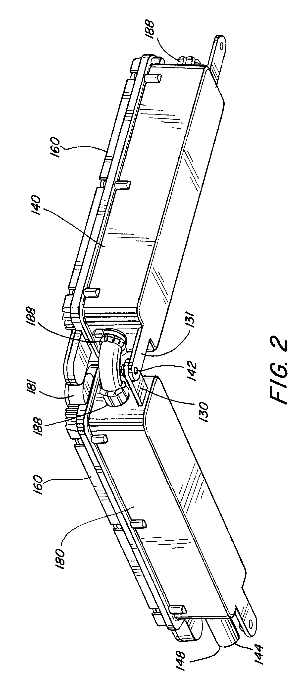
[0023]FIGS. 1-6 illustrate two generally elongated, box-shaped fixture components 140 and 180 which can be joined at selected arbitrary angles with respect to one another to provide highly configurable LED lighting arrangements. Each fixture component 140, 180, contains a plurality of LED light emitting diodes 143, with suitable heat sinking, e.g. 160. The heat sink component 160, as shown in FIG. 1, for example, is a unitary component bo...


PUM


Abstract

Concatenatable lighting fixtures, each comprising a unitary cover member having a circuit board mounting platform integrally formed with suitable heat sinking and which cover member mounts onto a cooperating base chassis. In one embodiment, the circuit board mounting platform extends farther from one end of the cover member than the other so as to facilitate placement of LEDs in a fashion which enhances lighting uniformity and minimizes dark spots. First and second guide members may be positioned in respective opposite ends of adjacent fixtures, each guide member having a plurality of extending fingers with a flexible electrical conductor-carrying conduit disposed between the respective opposite ends and retained in position by said fingers.

Description

[0001]This application claims the Paris Convention priority of U.S. Provisional Application No. 61 / 033,654 entitled “Modular LED Lighting Fixtures,” filed Mar. 4, 2008, the contents of which are hereby incorporated by reference in their entirety.BACKGROUND OF THE INVENTION[0002]1. Field of Invention[0003]This invention relates to the field of lighting technology and more specifically, to the use of LEDs in commercial and residential lighting fixtures.[0004]2. Description of Related Art[0005]Incandescent lighting has a low efficiency since much of the electrical power supplied to such lighting is converted to heat instead of light. The cost of electricity is expected to increase in the future as the cost of producing electricity rises. LEDs (light emitting diodes) provide a much more efficient conversion of electrical energy from incandescent lighting and efforts are underway to employ more efficient and longer lasting LED lamps in various applications.SUMMARY[0006]Embodiments hereaf...

Claims


Application Information

Patent Timeline
Patent Type & Authority Applications(United States)
IPC IPC(8): F21S4/00F21V21/00
CPCF21S2/005F21S4/008F21V21/005F21V23/002F21Y2101/02F21V29/767F21V27/02F21V29/004Y10S362/80F21V29/763F21Y2103/003F21V19/005F21S4/28F21Y2103/10F21Y2115/10
Inventor PEARSON, DENNISHORWITZ, TERRYHORVATH, RICHARD
Owner KORRUS INC
Why Eureka
Try Eureka