
Prediction of cardiac shape by a motion model

a motion model and shape technology, applied in the field of medical imaging of anatomical shapes, can solve problems such as the introduction of errors in the motion model of the model mesh, and achieve the effect of better modeling the motion of an individual mesh

Active Publication Date: 2009-09-17
KONINKLIJKE PHILIPS ELECTRONICS NV
View PDF6 Cites 10 Cited by
  • Summary
  • Abstract
  • Description
  • Claims
  • Application Information

AI Technical Summary

Benefits of technology

[0003]It would be advantageous to have a system capable of better modeling the motion of an individual mesh.
[0012]Typically, the propagated model mesh based on the propagation field comprising vectors of displacements of vertices of the second mean model mesh relative to respective vertices of the first mean model mesh better describes the modeled individual human heart at the second phase of cardiac cycle than the propagated model mesh based on the propagation field comprising vectors interpolated on the basis of vectors of displacements of vertices of the second mean model mesh relative to respective vertices of the first mean model mesh described in Ref. 1. This may be due to the fact that the vertex displacements of the mean model mesh can vary dramatically from vertex to vertex. Thus, the interpolated vertex displacements can often be less accurate than the mean model vertex displacements used by the system of the invention. Consequently, the system of the invention improves modeling the motion of the individual human heart. Advantageously, the propagation field of the mean model vertex displacement vectors is straightforward to compute and to apply.

Problems solved by technology

Unfortunately, the interpolated displacement vectors introduce errors into the model of motion of the model mesh.

Method used


Image

  • Prediction of cardiac shape by a motion model
  • Prediction of cardiac shape by a motion model
  • Prediction of cardiac shape by a motion model

Examples


Embodiment Construction

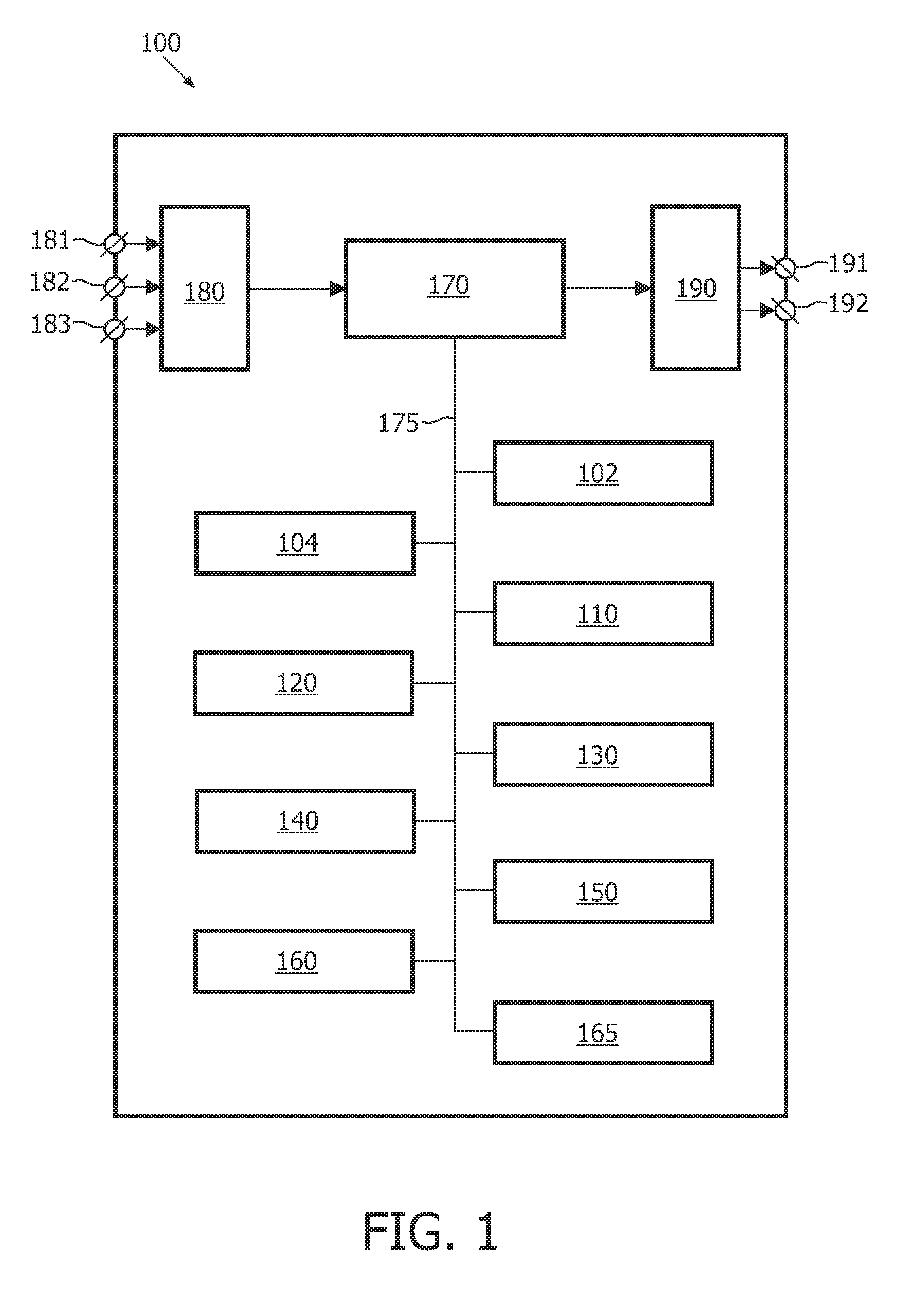
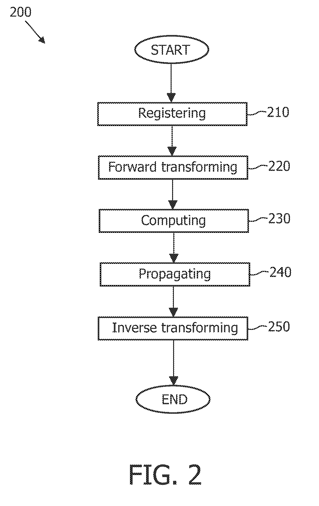
[0052]FIG. 1 schematically shows a block diagram of an exemplary embodiment of the system for propagating a model mesh based on a first mean model mesh and on a second mean model mesh, the system comprising:[0053]a registration unit 110 for computing a registration transformation for registering the first model mesh with the first mean model mesh;[0054]a forward transformation 120 unit for transforming the model mesh into a registered model mesh using the registration transformation;[0055]a computation unit 130 for computing a propagation field for propagating the registered model mesh, the propagation field comprising vectors of displacements of vertices of the second mean model mesh relative to respective vertices of the first mean model mesh;[0056]a propagation unit 140 for transforming the registered model mesh into the propagated registered model mesh based on applying the vertex displacement vectors of the propagation field to respective vertices of the registered model mesh; ...


PUM


Abstract

The invention relates to a system (100) for propagating a model mesh based on a first mean model mesh and on a second mean model mesh, the system comprising: a registration unit (110) for computing a registration transformation for registering the first model mesh with the first mean model mesh; a forward transformation unit (120) for transforming the model mesh into a registered model mesh using the registration transformation; a computation unit (130) for computing a propagation field for propagating the registered model mesh, the propagation field comprising vectors of displacements of vertices of the second mean model mesh relative to respective vertices of the first mean model mesh; a propagation unit (140) for transforming the registered model mesh into the propagated registered model mesh based on applying the vertex displacement vectors comprised in the propagation field to respective vertices of the registered model mesh; and an inverse transformation unit (150) for transforming the propagated registered model mesh into the propagated model mesh using the inverse of the registration transformation, thereby propagating the model mesh. Using the propagation field comprising vectors of displacements of vertices of the second mean model mesh relative to respective vertices of the first mean model mesh improves modeling motion of anatomical shapes. Advantageously, the propagation field of vertex displacement vectors is straightforward to compute and to apply.

Description

FIELD OF THE INVENTION[0001]The invention relates to the field of medical imaging of an anatomical shape and more specifically to modeling motion of the anatomical shape.BACKGROUND OF THE INVENTION[0002]A method of modeling motion of the human heart is described by C. Lorenz and J. von Berg in an article entitled “Towards a comprehensive geometric model of the heart” published in FIMH, Proceeding of the Third international Workshop, pages 102-112, Springer-Verlag 2005, hereinafter referred to as Ref. 1. In this article, the human heart is described by a model mesh. The motion of the model mesh from a first phase of cardiac cycle to a second phase of cardiac cycle is described using a model space transformation. The model space transformation is estimated using smooth interpolation, e.g. thin-plate-splines interpolation, of a potentially sparse deformation field comprising displacements of a set of cardiac landmarks of a reference model, for which the displacement vectors are known. ...

Claims


Application Information

Patent Timeline
IPC IPC(8): G06T17/00
CPCG06T7/0028G06T2207/30048G06T2207/10072G06T7/20G06T7/33
Inventor VON BERG, JENSLORENZ, CRISTIAN
Owner KONINKLIJKE PHILIPS ELECTRONICS NV
Learn More