Fuel cell stack structure

Inactive Publication Date: 2009-09-17
NISSAN MOTOR CO LTD
View PDF7 Cites 8 Cited by
  • Summary
  • Abstract
  • Description
  • Claims
  • Application Information

AI Technical Summary

Benefits of technology

[0005]Furthermore, in the above stack structure, for the purposes of improving startability and responsibility at the transient operation and reducing energy required for heating at the start to increase a total efficiency of operations including start and stop, or for the purpose of increasing stacking density of the stack to increase output density, the central sections of the cell plate and the separator plate are made thin in some cases to reduce heat capacity. However, the stack structure could be subject to creep deformation due to thermal stress caused by a difference in coefficient of thermal expansion between the central sections of the cell plate and the separator plate and the sealing members when the stack structure repeatedly increases and decreases in

Problems solved by technology

In the case of the fuel cell stack structure of U.S. Pat. No. 6,344,290, both gases of fuel gas and air are supplied through central sections of cell plates and separator plates and exhausted through outer peripheries, and thus unburned gas cannot be recovered.
Furthermore, in such a case, unstable combustion in the outer periphery causes local thermal stress in single cells, and the single cells could be damaged.
However, the stack structure

Method used


Image

  • Fuel cell stack structure
  • Fuel cell stack structure
  • Fuel cell stack structure

Examples


Embodiment Construction

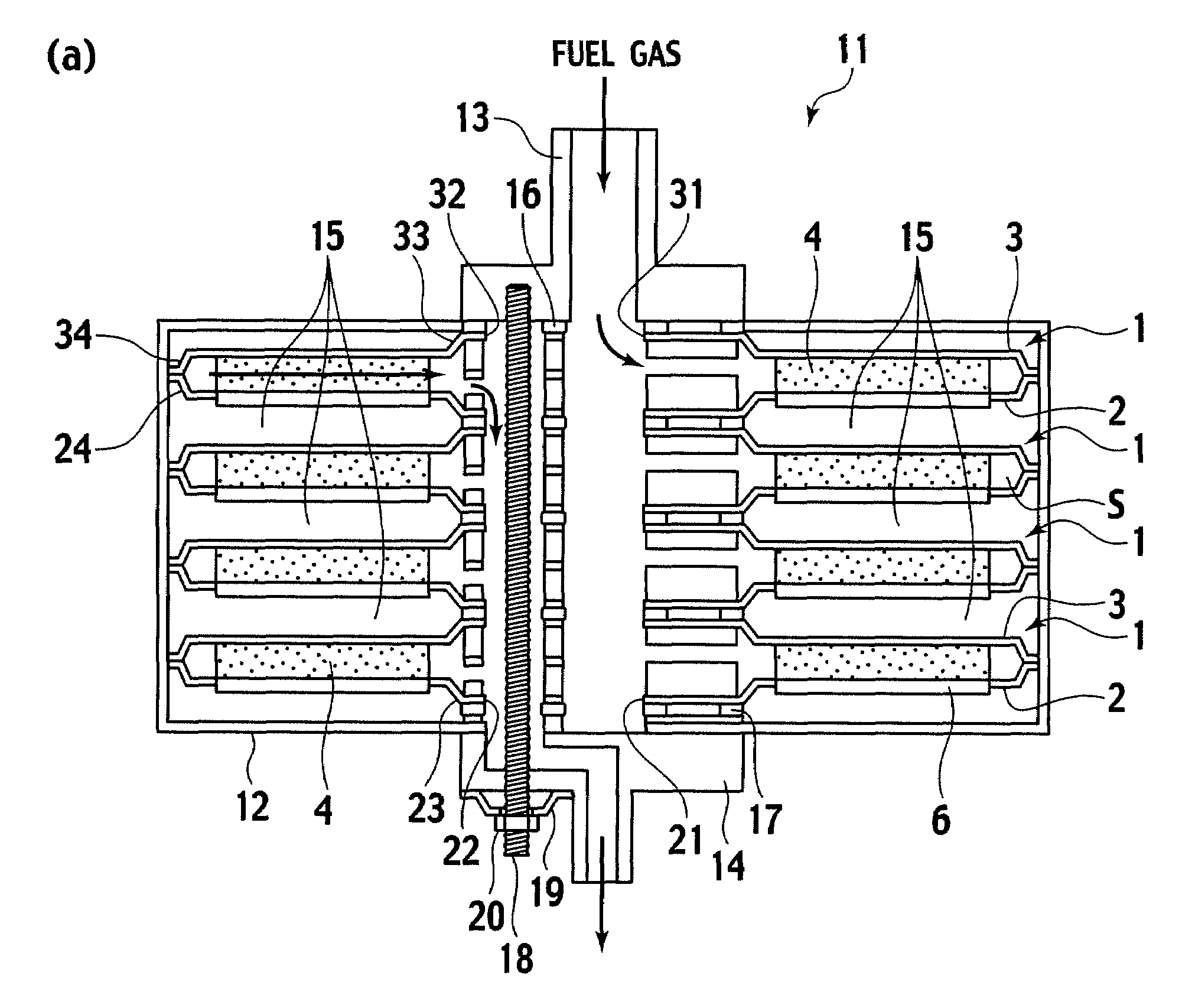
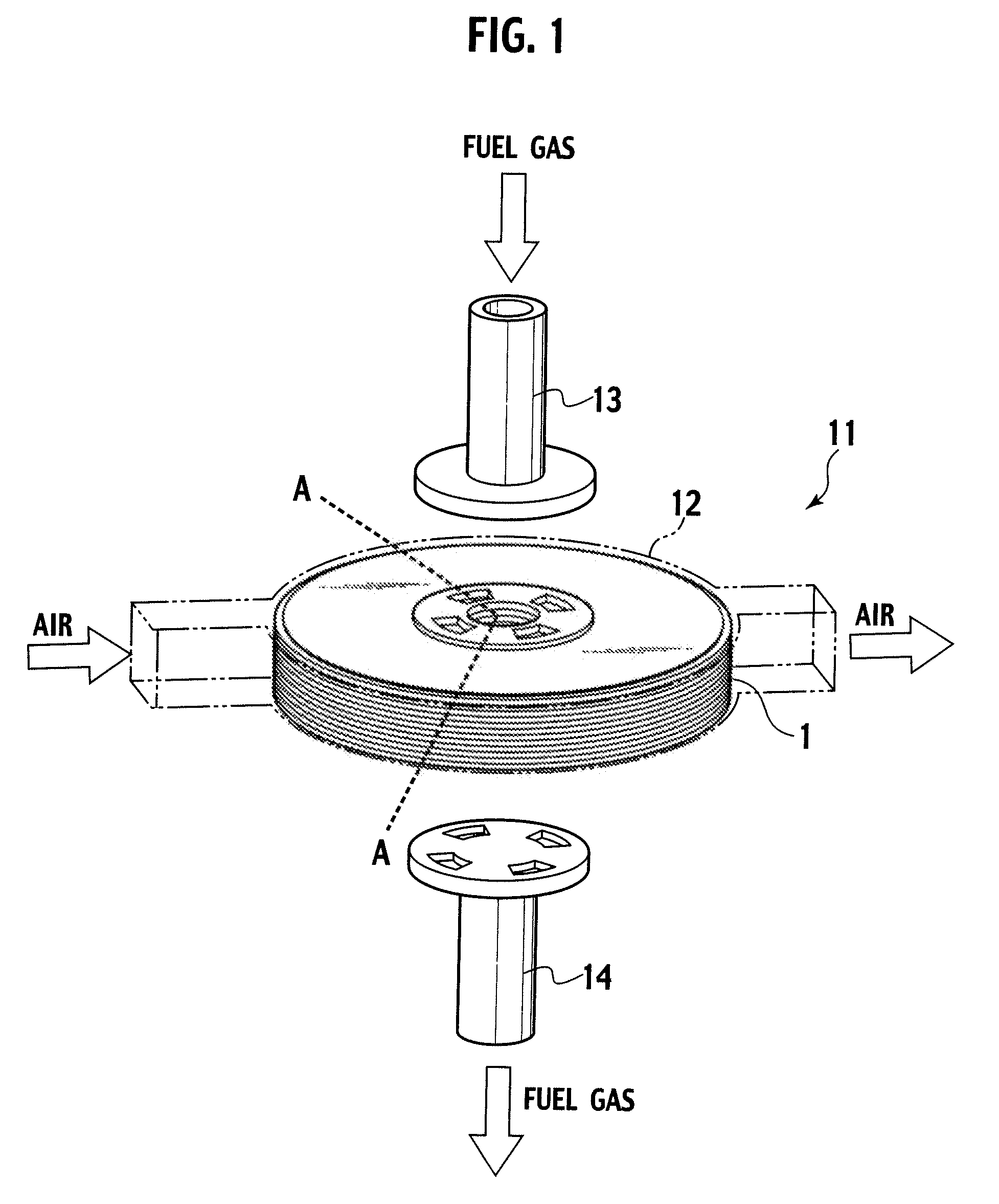
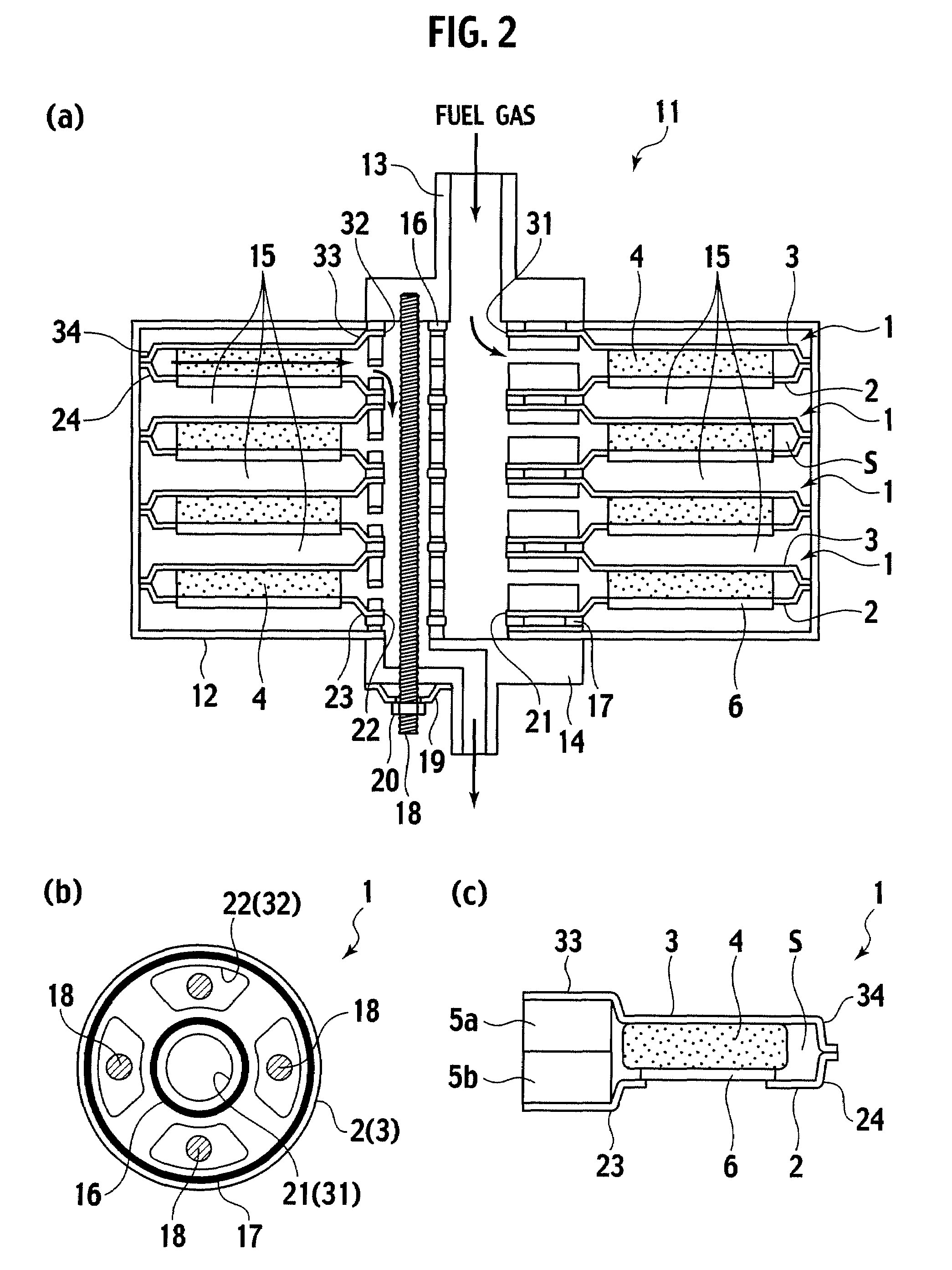
[0020]A fuel cell stack structure (hereinafter, also referred to as just a stack structure) of the present invention is composed of a plurality of solid oxide fuel cells (hereinafter, also referred to as just fuel cells) which are stacked facing a same direction. Each of the fuel cells includes a separator plate and a cell plate joined to each other. The cell plate is circular, holds single cells, and has a gas introducing opening and a gas exhausting opening in a central section thereof. The separator plate is circular and has a gas introducing opening and a gas exhausting opening in a central section thereof. An outer peripheral edge of the separator plate is joined to an outer peripheral edge of the cell plate.

[0021]Furthermore, at least one of the cell plate and the separator plate includes a step along the outer peripheral edge thereof, and the step forms a space between the cell plate and the separator plate.

[0022]In between the central sections of the cell plate and the separ...


PUM


Abstract

In a plurality of solid oxide fuel cells (1) each including: a circular cell plate (2) holding single cells (6) as a solid oxide fuel cells and having a gas introducing opening (21) and a gas exhausting opening (22) in a central section; a circular separator plate (3) having a gas introducing opening (31) and a gas exhausting opening (32) in a central section and joined to the cell plate; and a central channel member (5) which is located in a space (S) formed by steps of the cell plate and the separator plate and performs supply and exhaust of fuel gas, a plurality of the solid oxide fuel cells are stacked facing a same direction, a interspace between each adjacent pair of the overlapping fuel cells serves as an air channel (15), sealing members (16) (17) allowing the gas intruding openings of the cell plate and the separator plate to airtightly communicate with each other and allowing the gas exhausting openings of the cell plate and the separator plate to airtightly communicate with each other are provide between the center parts of the fuel cells, and the stacked fuel cells are fastened and fixed by a bolt (18) at the center.

Description

TECHNICAL FIELD[0001]The present invention relates to a fuel cell stack structure composed of a plurality of solid oxide fuel cells stacked.BACKGROUND ART[0002]Conventional fuel cell stack structures each composed of a plurality of solid oxide fuel cells stacked are disclosed by U.S. Pat. No. 6,344,290 and Japanese Patent Unexamined Publication No. 2002-151106.DISCLOSURE OF INVENTION[0003]In the case of the fuel cell stack structure of U.S. Pat. No. 6,344,290, both gases of fuel gas and air are supplied through central sections of cell plates and separator plates and exhausted through outer peripheries, and thus unburned gas cannot be recovered. Accordingly, in the case where the gas flow varies, such as at transient operation, the fuel utilization is reduced, and the power generation efficiency is reduced. Furthermore, in such a case, unstable combustion in the outer periphery causes local thermal stress in single cells, and the single cells could be damaged.[0004]Moreover, the abo...

Claims


Application Information

Patent Timeline
IPC IPC(8): H01M8/10
CPCH01M8/0247H01M8/04097H01M8/243Y02E60/525H01M2008/1293Y02E60/50H01M8/248H01M8/2432H01M8/2483
Inventor KUSHIBIKI, KEIKONAKAJIMA, YASUSHIIBUKA, SHIGEOKOMATSU, HIROKAZUYAGUCHI, TATSUYA
Owner NISSAN MOTOR CO LTD
Why Eureka
Try Eureka