
Device attachable to a surgical suturing machine for forming an end-to end anastomosis on two hollow organs

a technology for hollow organs and sutures, which is applied in the field of devices can solve the problems of unoptimized and unfavorable endoscopic suturing machines for forming end-to-end anastomoses on two hollow organs

Active Publication Date: 2009-09-17
KARL STORZ GMBH & CO KG
View PDF4 Cites 4 Cited by
  • Summary
  • Abstract
  • Description
  • Claims
  • Application Information

AI Technical Summary

Benefits of technology

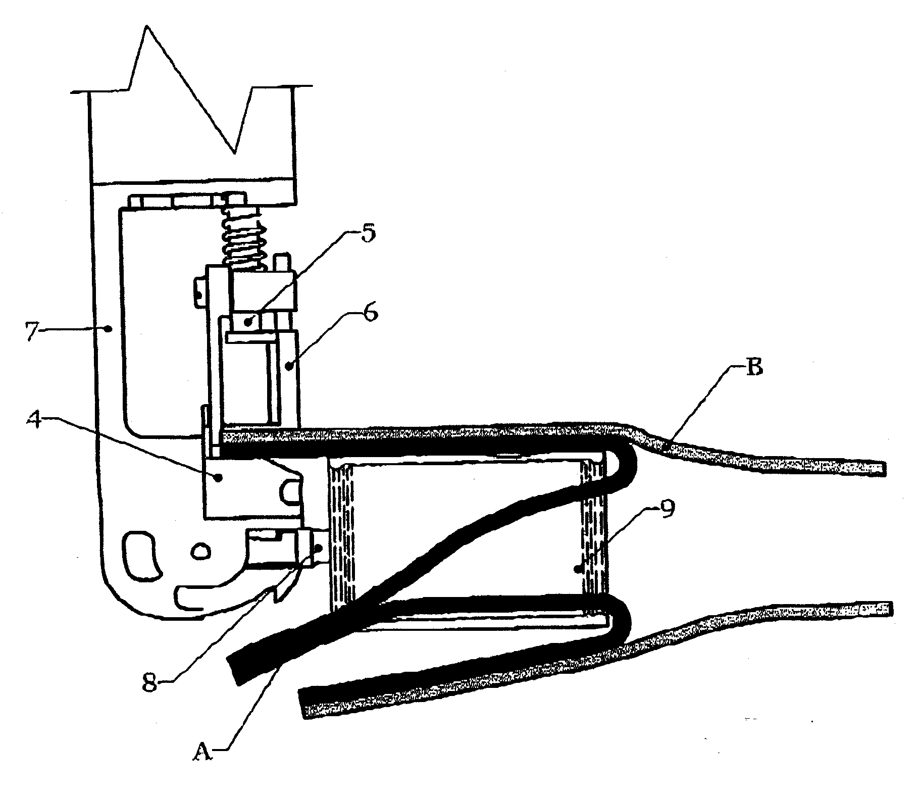
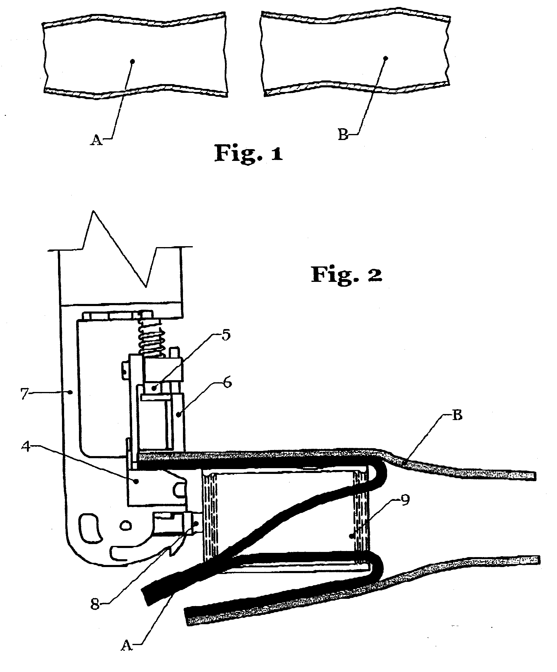
[0013]Consequently, it is possible to introduce the first hollow organ into the carrier in such a way that its edge area protrudes opposite the carrier by a defined amount and the protruding edge area can be pulled back over the carrier in such a way that the outside of the hollow organ lies on or rests on the outside of the carrier, whereby the edge zone of the hollow organ is located under the needle and it rests on the needle plate. Then, the edge area of the second hollow organ can be pushed so far onto the pulled-back area of the first hollow organ until its edge zone is likewise located under the needle and marginally equal to the edge zone of the first hollow organ and rests with its inside on the inside of the first hollow organ. In this position of the two hollow organs, the seam connecting the edge areas of the two hollow organs can be formed by means of the surgical suturing machine within the edge zones of the two hollow organs. The two hollow organs are to be moved further under the removed needle at the end of each stitch formation each time by an amount corresponding to the stitch length of the seam. After completion of the seam, the two hollow organs, which have their essentially cylindrical shape during the suturing, may be pressed somewhat flat in the short term, so that the first hollow organ can be moved out of the carrier through the longitudinal slot provided in the carrier and can be brought into a stretched position.
[0017]A structurally simple solution for the diversion of the rotary movement of the sleeve by the drive of the suturing machine arises when the sleeve has teeth on one of its faces, with which a driving pawl mounted at the carrier cooperates, which can be connected to the drive of the needle bar or of the push rod in a driven manner by means of a deformable transmission means.
[0019]To achieve the diversion of the movement of the sleeve by the pivoting movement of the driving pawl, it is advantageous if this driving pawl is arranged off-center to the sleeve and meshes with its teeth in a nonpositive manner, such that a phased, intermittent rotary movement of the sleeve can be diverted by the pivoting movements of the driving pawl.
[0021]This is advantageously achieved in that the bracket for the carrier is formed by an angular carrying piece, whose first arm can be connected via a first lockable hinge connection to a spacer fastened to the house of the surgical suturing machine, and whose second arm can be connected to the carrier by means of a second, likewise lockable hinge connection, and the bracket can be moved from the position securing the operating position of the carrier into a position, in which the carrier is directed essentially parallel to the longitudinal axis of the suturing machine.

Problems solved by technology

Thus, this endoscopic suturing machine is suitable for connecting lips, which lie flat on each other or next to each other, to each other by means of a seam of the above-described type and thus for replacing the manual seam formation; however, this endoscopic suturing machine is not provided for forming end-to-end anastomoses on two hollow organs and hence is not optimal.

Method used


Image

  • Device attachable to a surgical suturing machine for forming an end-to end anastomosis on two hollow organs
  • Device attachable to a surgical suturing machine for forming an end-to end anastomosis on two hollow organs
  • Device attachable to a surgical suturing machine for forming an end-to end anastomosis on two hollow organs

Examples


Embodiment Construction

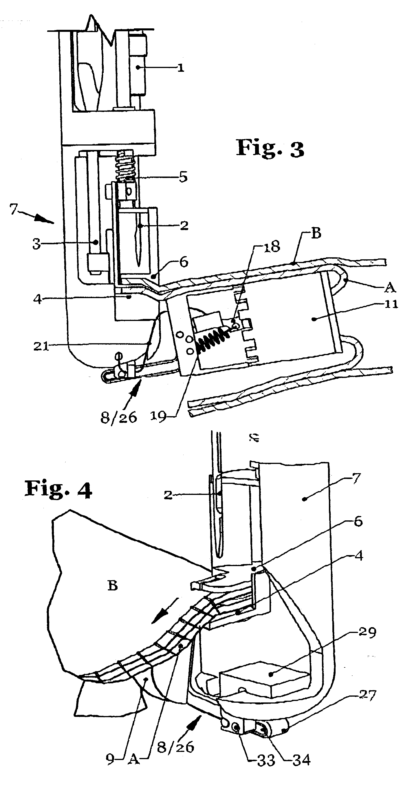
[0036]Referring to the drawings in particular, the lower area of a surgical suturing machine, as it is shown and described, for example, in DE 101 16 171 A1 or EP 1 372 490 B1, is shown in FIG. 3.

[0037]This suturing machine has a motor driven needle bar 1 along with a thread-carrying needle 2, which cooperates with a shuttle to form a chain stitch seam of the stitch type 501 or a stitch type similar hereto. The stitch formation, which is not of further interest in detail here, is shown in FIGS. 8 through 12 of the above-mentioned publications and is also explained in detail in the specification.

[0038]Besides the needle 2 and the (not shown) shuttle attached to a shuttle bar 3, the suturing machine has a needle plate 4 with a slot-like stitch hole and a holding-down device 6 accommodated by a push rod 5, likewise provided with a slot, for the hollow organs A, B, which holding-down device is periodically raised depending on the movement of the needle 2 to facilitate the feed movement ...


PUM


Abstract

A process and a device are provided for forming an end-to-end anastomosis on two hollow organs, which can be attached to a surgical suturing machine with at least one driven needle bar with a thread-carrying needle, a shuttle cooperating with this needle, a needle plate and a holding-down device accommodated by a push rod. A carrier (9) is provided designed as a hollow cylinder and has a longitudinal slot (13) for the edge areas of the two hollow organs. The carrier can be connected by means of a bracket to the housing shaft of the suturing machine in such a way that its longitudinal axis runs transversely to the path of movement of the needle, and its contact area for the two hollow organs is directed essentially parallel to the plane of the contact surface of the needle plate of the suturing machine.

Description

CROSS REFERENCE TO RELATED APPLICATIONS[0001]This application is a United States National Phase application of International Application PCT / EP2007 / 009611 and claims the benefit of priority under 35 U.S.C. § 119 of German Patent Application DE 10 2006 053 217.1 filed Nov. 9, 2006, the entire contents of which are incorporated herein by reference.FIELD OF THE INVENTION[0002]The present invention pertains to a device for forming an end-to-end anastomosis on two hollow organs, which can be attached to a surgical suturing machine with at least one motor-driven needle bar with a thread-carrying needle, a shuttle cooperating with this needle, a needle plate and a holding-down device for the material to be sutured accommodated by a push rod.BACKGROUND OF THE INVENTION[0003]In medical engineering, it is common in certain diseases of hollow organs, to cut out sick areas of same, for example, sick intestinal areas and to reconnect the two cut ends to each other. Thus, for example, the intesti...

Claims


Application Information

Patent Timeline
IPC IPC(8): A61B17/11
CPCA61B17/0469A61B17/11A61B17/0491
Inventor FRINGS, HERMANN-JOSEFMOLL, CLEMENSMOLL, PHILIPP
Owner KARL STORZ GMBH & CO KG
Learn More