Clamp for plural wire harnesses

a technology of wire harnesses and clamps, applied in the field of clamps, can solve the problem of low cost of each clamping devi

Inactive Publication Date: 2009-09-24
NEWFREY
View PDF7 Cites 17 Cited by
  • Summary
  • Abstract
  • Description
  • Claims
  • Application Information

AI Technical Summary

Benefits of technology

[0012]An aspect of the present invention is to provide a wire harness clamp in which a plurality of wire harnesses can be retained without being able to move in the axial direction or in the direction perpendicular to the axial direction such as when a plurality of wire harnesses is wrapped with tape but without requiring the wire harnesses to be wrapped with tape.
[0014]In the clamp of an exemplary embodiment, the entire periphery of the plurality of wire harnesses accommodated in the U-shaped groove may be surrounded with pressure applied elastically from the inner wall surface of the U-shaped groove and a harness pressing tab to keep the wire harnesses from sliding axially and to keep them from moving in the direction perpendicular to the axial direction. Because this has the same effect as wrapping a plurality of wire harnesses with tape, it eliminates the cumbersome tape wrapping operation. The same clamp can also be used to retain different numbers of wire harnesses. A plurality of protruding ribs is formed on the inner wall surface on the bottom surface side of the holding portion main unit and extend lengthwise with respect to the wire harnesses from the mid-height position of the U-shaped groove to align the wire harnesses so as to be stacked from the bottom surface, and the open portion above the mid-height position of the U-shaped groove is wide enough to accommodate more wire harnesses above the mid-height position. As a result, the wire harnesses do not have to be aligned beforehand, but can be aligned by the U-shaped groove in the holding portion main unit and secured in a taut configuration. Also, because the holding portion main unit has a simple configuration, the cost of each clamp is low.

Problems solved by technology

Also, because the holding portion main unit has a simple configuration, the cost of each clamp is low.

Method used


Image

  • Clamp for plural wire harnesses
  • Clamp for plural wire harnesses
  • Clamp for plural wire harnesses

Examples


Embodiment Construction

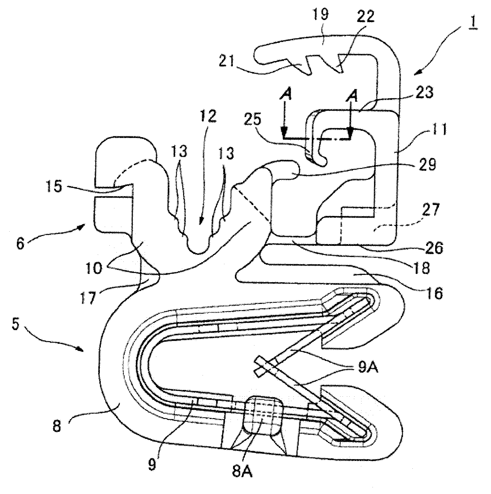
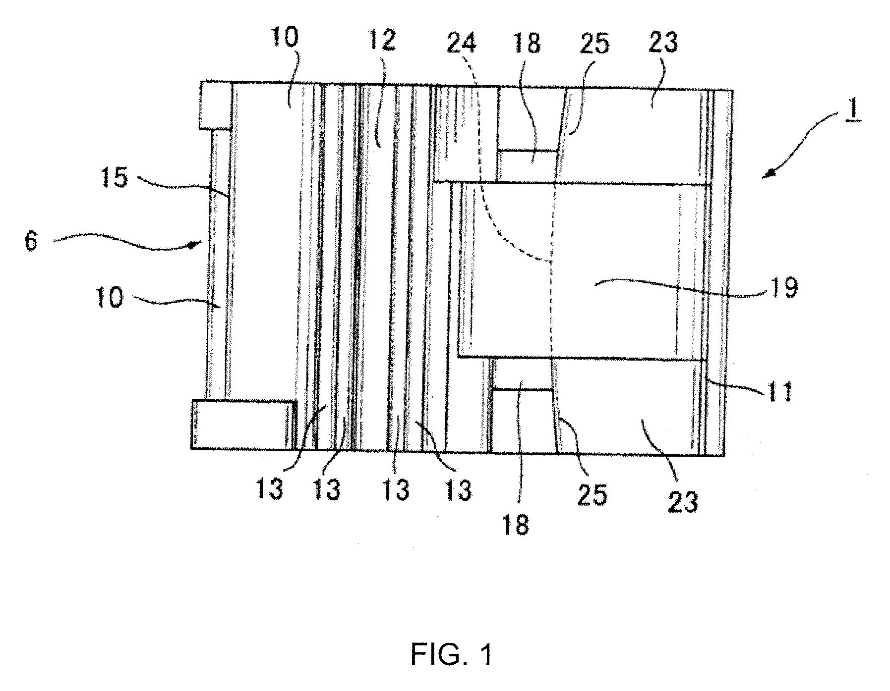
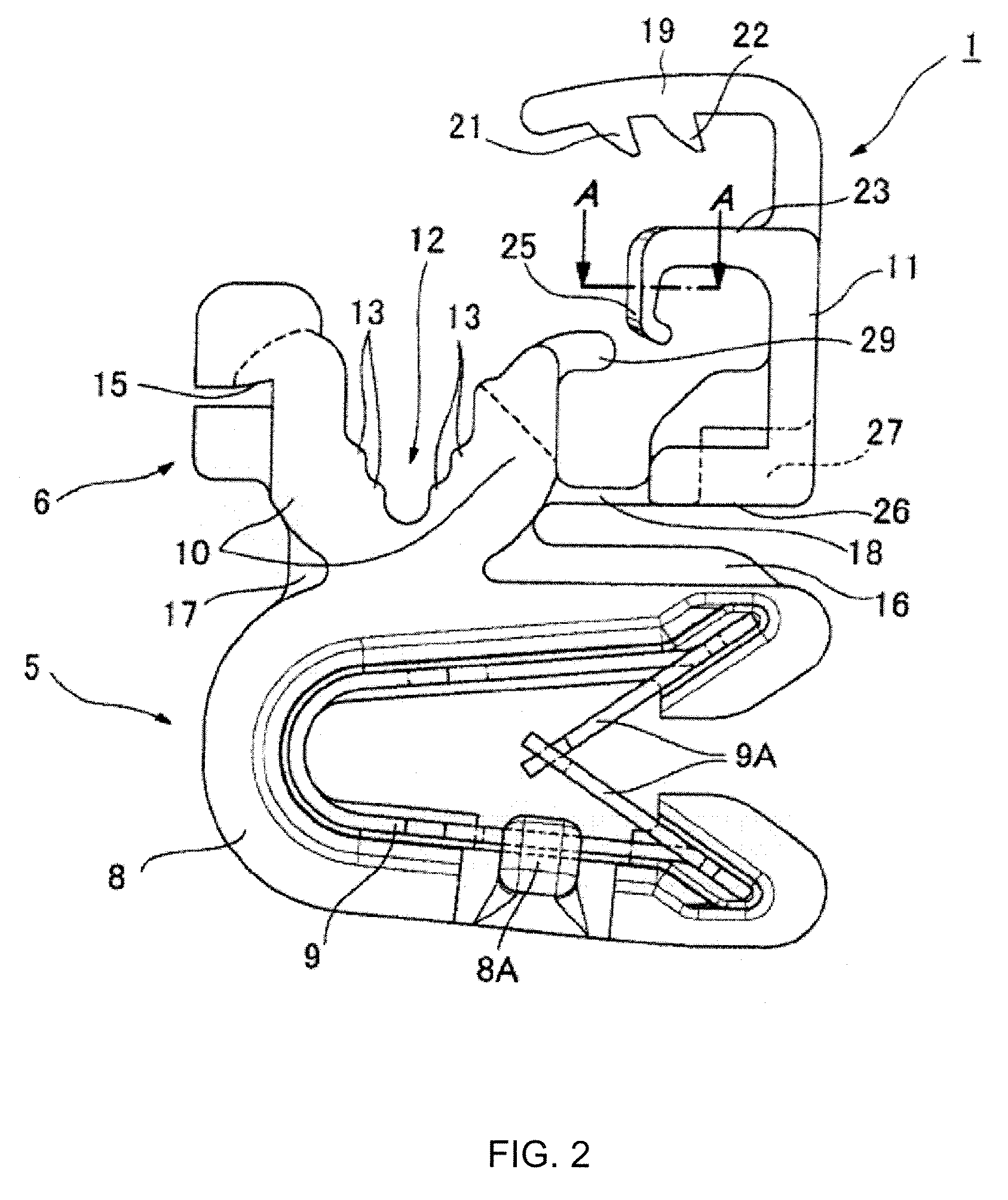
[0024]The following is an explanation with reference to the figures of the clip for a plurality of wire harnesses in an exemplary embodiment of the present invention. FIG. 1, FIG. 2 and FIG. 3 are a plan view, front view and side view of the clamp 1, and FIG. 4 is a cross-sectional view of the clamp 1 from A-A in FIG. 2. The entire clamp 1 is integrally molded using a hard plastic except for the metal holding tab 9 in the panel fixing portion 5. The metal holding tab 9 is connected to the panel fixing portion 5. In FIG. 5, three wire harnesses 3 are attached to a panel 2 mounting component using the clip 1. In FIG. 6, six wire harnesses 3 are held in the clip 1.

[0025]The following is an explanation of the configuration of the clip 1 with reference to FIG. 1 through FIG. 4. The clip 1 comprises a panel fixing portion 5 and a wire harness holding portion 6. The panel fixing portion 5, as shown in FIG. 5, holds a plate-shaped mounting portion 7 standing erect from the panel 2. In order...


PUM


Abstract

A clamp including a panel fixing portion and a wire harness holding portion. The wire harness holding portion includes a holding portion main unit with a U-shaped groove with an open upper portion and a cover portion. A plurality of protruding ribs are formed on the inner wall surface on the bottom surface side of the holding portion main unit and extend lengthwise with respect to the wire harnesses from the mid-height position of the U-shaped groove, the open portion upward from the mid-height position of the U-shaped groove being wide enough to accommodate more wire harnesses above the mid-height position. The cover portion is formed with an elastic harness pressing tab for elastically pressing down on the upper portion of the wire harnesses, so that the entire outer periphery of the wire harnesses are elastically pressed down upon when covered.

Description

CROSS-REFERENCE TO RELATED APPLICATIONS [0001]This application claims the benefit of Japanese Application No. 2008-69676 filed Mar. 18, 2008, the disclosure of which is incorporated herein by reference.TECHNICAL FIELD [0002]The present invention relates to a clamp for securely holding a plurality of wire harnesses in a manner similar to wrapping with tape, regardless of the number of wire harnesses.BACKGROUND ART [0003]It is common to wrap a plurality of wire harnesses with tape to secure the wire harnesses to a mounting component such as a panel.[0004][Patent Document 1] Published Unexamined Utility Model Application No. 5-047666[0005][Patent Document 2] Published Unexamined Utility Model Application No. 7-002690[0006][Patent Document 3] Published Unexamined Patent Application No. 7-059232[0007][Patent Document 4] Published Unexamined Patent Application No. 2006-187095[0008][Patent Document 5] Published Unexamined Patent Application No. 2005-113953[0009]Patent Document 1 describes ...

Claims


Application Information

Patent Timeline
Patent Type & Authority Applications(United States)
IPC IPC(8): A47B96/06
CPCB60R16/0215H02G3/32F16L3/1075F16B2/22
Inventor MATSUNO, HIROTOSAKAKIBARA, KIYOHITO
Owner NEWFREY
Why Eureka
Try Eureka