Device for Indicating Illicit Substances in the Exhalation Air of a Machine Operator

a machine operator and exhalation air technology, applied in the direction of material analysis, instrumentation, driver input parameters, etc., can solve the problems of increased risk of accidents, no current use system has any check function, and persons with a decreased lung capacity may experience difficulty in giving an approved sampl

a machine operator and exhalation air technology, applied in the direction of material analysis, instrumentation, driver input parameters, etc., can solve the problems of increased risk of accidents, no current use system has any check function, and persons with a decreased lung capacity may experience difficulty in giving an approved sampl

US20090236527A1Inactive Publication Date: 2009-09-24SIGNALTEKNIK I STOCKHOLM

Image

  • Device for Indicating Illicit Substances in the Exhalation Air of a Machine Operator
  • Device for Indicating Illicit Substances in the Exhalation Air of a Machine Operator

Examples


Embodiment Construction

[0011]The invention will now be described in detail by means of an example and referring to the enclosed drawing in which:

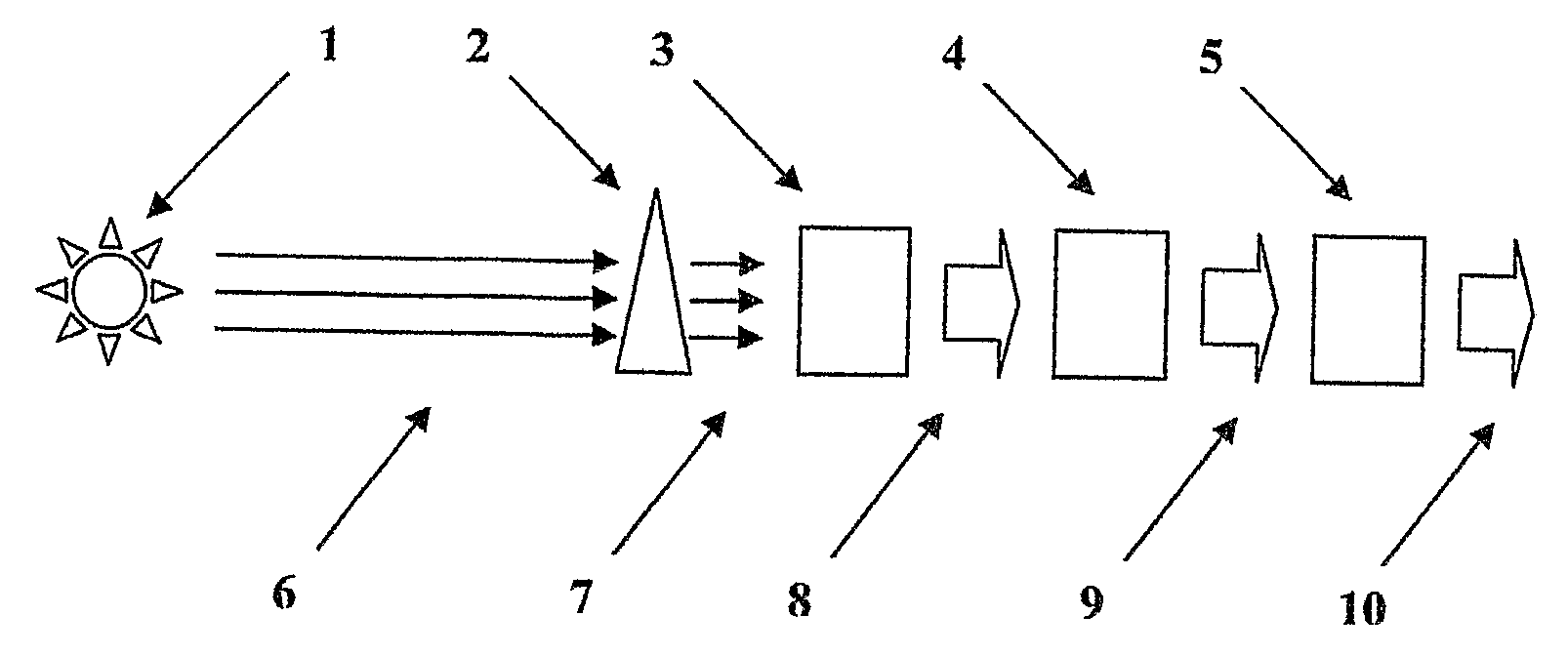
[0012]FIG. 1 schematically shows a device according to the invention and

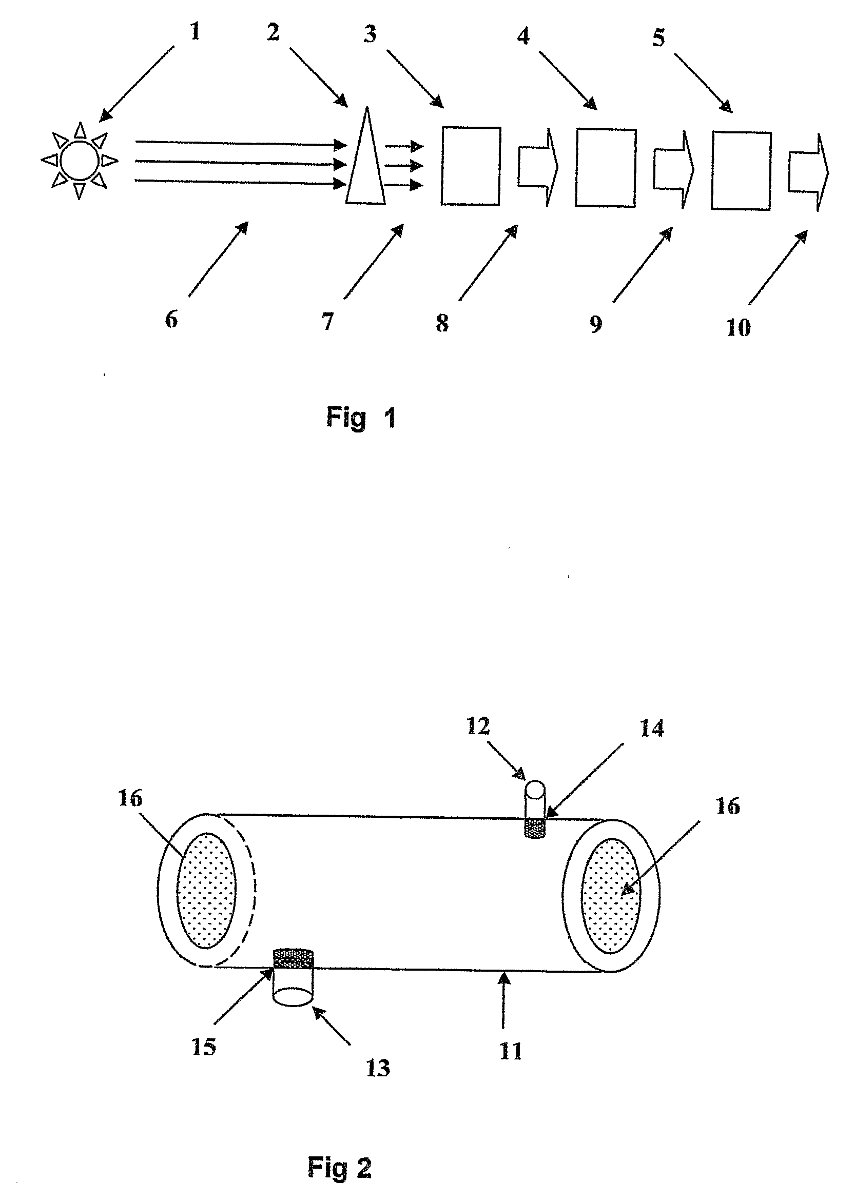
[0013]FIG. 2 schematically shows a sampling chamber to be used in the device according to the invention for carrying out an active exhalation sample or for calibration / verification or analysis of another gas sample.

[0014]In FIG. 1 reference 1 denotes an IR source transmitting a light beam 6 through the air to be analyzed. The beam path 6 is arranged closed to the face of an operator (not shown), e.g. a vehicle driver, and reaches one or several optical analysers 2 located in front of an IR detector 3 measuring the intensity of the IR light. According to the example the optical filters 2 are adapted to wavelengths having a high absorption for ethanol and a reference wavelength not being affected by ethanol and the IR source and the optical filters are stationary mounted in front of the driver ...


PUM

PropertyMeasurementUnit
wave lengthaaaaaaaaaa
IR absorbanceaaaaaaaaaa
concentrationaaaaaaaaaa

Abstract

A device for a continuous indication of illicit substances in the exhalation air of face of the machine operator comprises an IR source and an IR detector being sensitive to wave length having an absorbance of the illicit substance, whereby the beam path of the IR source to the detector runs in front of the face of the operator.

Description

FIELD OF THE INVENTION[0001]The present invention refers to an advice for indicating illicit substances such as ethanol in the exhalation air of a machine operator e.g. a driver of a vehicle.BACKGROUND OF THE INVENTION[0002]Operators / drivers of vehicles, boats, aircraft, trains, traverses and other machines are in a position demanding tense watchfulness and high reaction ability so as not to cause accidents. The influence of different substances, such as alcohol may seriously deteriorate judgment, time of reaction and also other abilities giving rise to an increased risk for accidents.[0003]So called alcohol interlocks were initially used in Canada and the US and are now also in use e. g. in Sweden. Initially the systems were only used in vehicles used by persons convicted in court to install them in order to keep their drivers' licenses. The monitoring system implied that they should, within short intervals, visit a service firm which scrutinized the information stored in the syste...

Claims


Application Information

Patent Timeline
24 Sep 2009
Publication
US20090236527A1
IPC
G01N33/497; G01N21/35
CPC
B60K28/06; G01N33/4972; G01N21/3504; B60W2540/24
Inventors
SJODIN, KURT; HEDMAN, ADAM