Eureka AIR delivers breakthrough ideas for toughest innovation challenges, trusted by R&D personnel around the world.

Feed assist assembly

a technology of feed roller and assembly, applied in the field of media feedpath, can solve the problems of additional resistive forces on the feed roller nip, print or scan defects, etc., and achieve the effect of reducing resistive forces

Inactive Publication Date: 2009-09-24
LEXMARK INT INC
View PDF6 Cites 4 Cited by
  • Summary
  • Abstract
  • Description
  • Claims
  • Application Information

AI Technical Summary

Benefits of technology

[0011]A feed assist media feedpath assembly comprises a media feedpath having a media input, a C-shaped portion downstream of the media input, and a feed nip downstream of the C-shaped portion, a feed assist roller positioned between the C-shaped portion and the feed nip for feeding media, the feed assist roller not having an opposed pinch roller, the feed assist roller being over-driven relative to a driven roller of the feed roll nip, a toggle gear train assembly driving the feed assist roller in a forward direction or disengaging the feed assist roller when the driven roller is reversed. The feed assist roller creating a load buffer in the media between the feed assist roller and the feed roll nip. The load buffer being a slight buckle in the media for reducing resistive forces on the feed roll nip. The media feedpath comprising a simplex feedpath portion. The feed assist media feedpath further comprising a duplex feedpath portion. The feed assist roller disposed at a junction between the simplex path and the duplex path.

Problems solved by technology

The sum of forces applied by these other roller nips acting on the media introduces resistive forces on the feed roller nip which may cause print or scan defects.
Also, C-shaped feedpaths cause additional resistive forces on the feed roller nip due to the bending of the media in passing through the feedpath.

Method used


Image

  • Feed assist assembly
  • Feed assist assembly
  • Feed assist assembly

Examples


Embodiment Construction

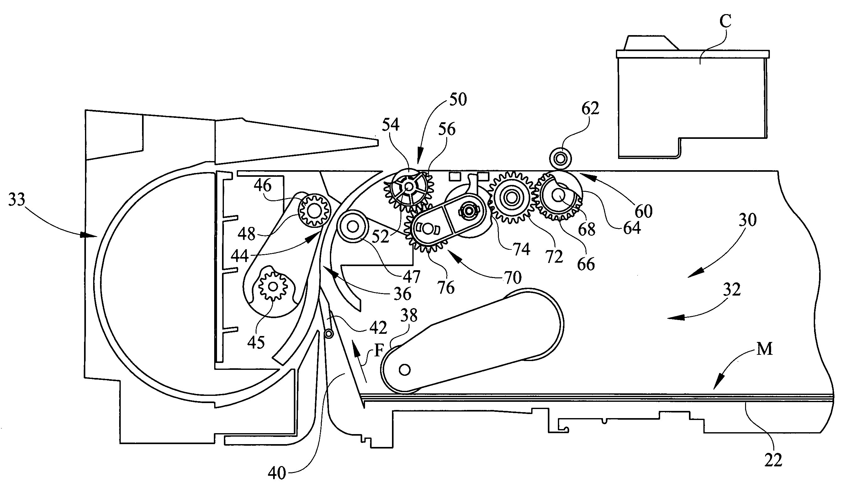
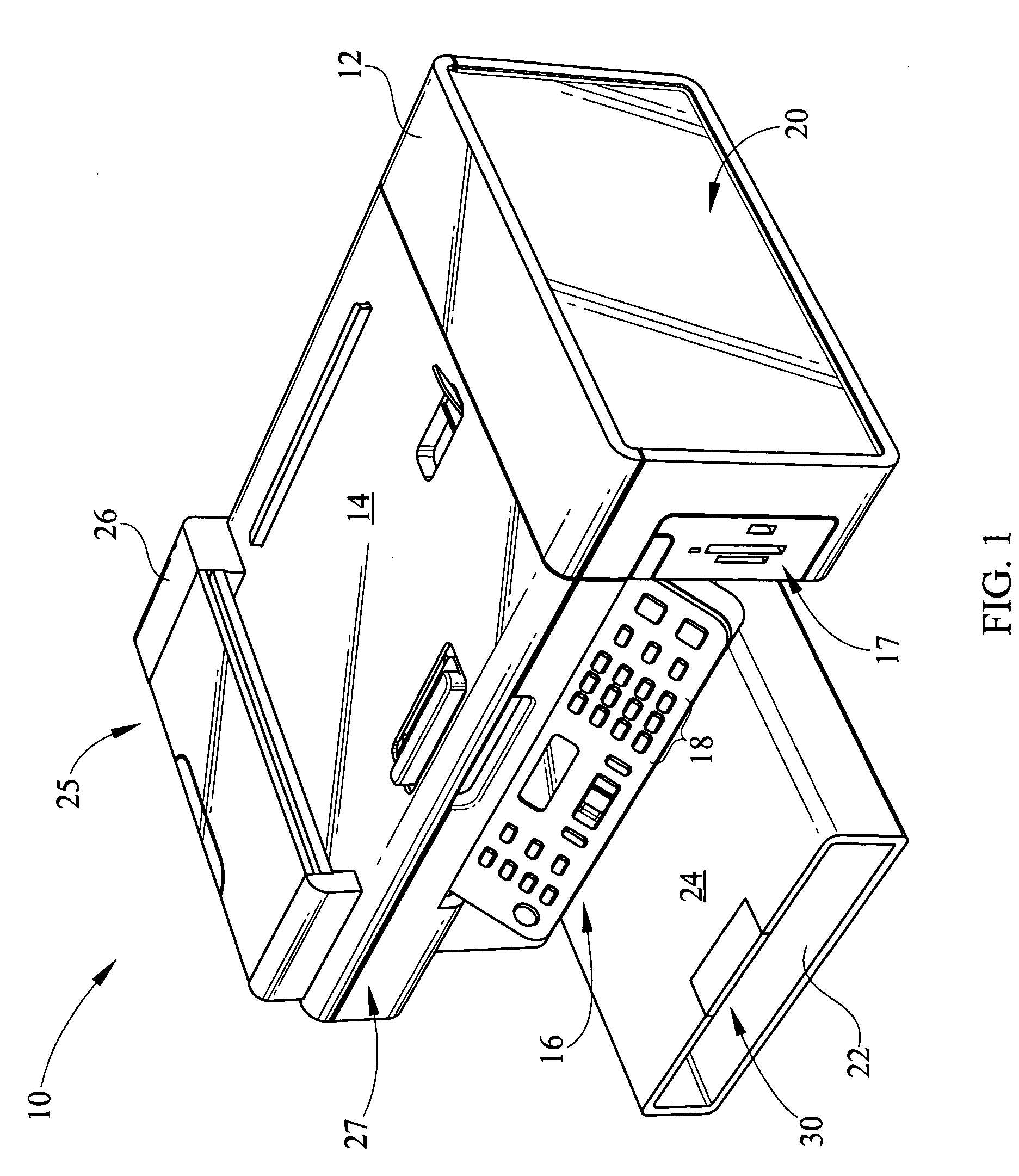
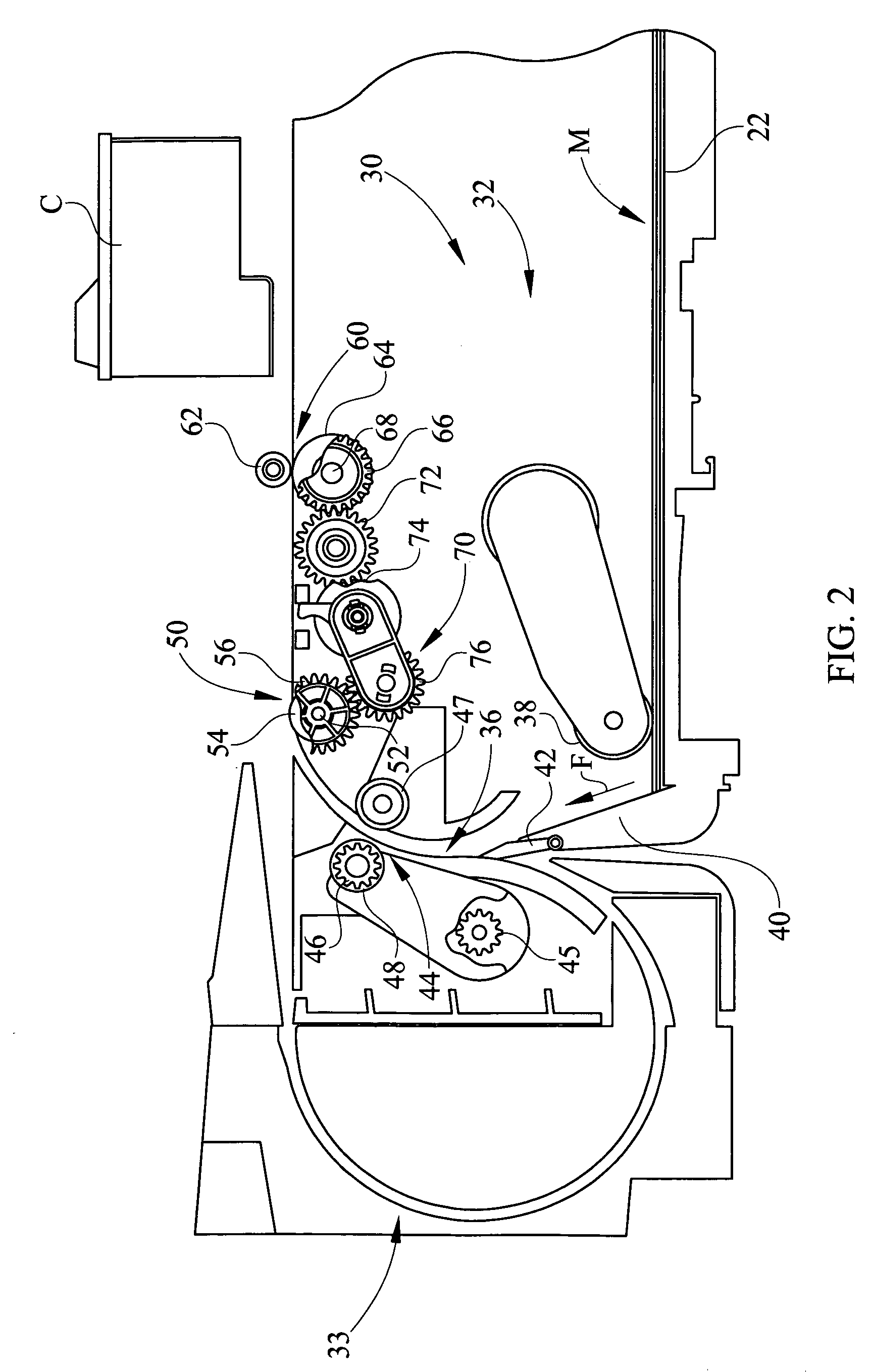
[0021]It is to be understood that the invention is not limited in its application to the details of construction and the arrangement of components set forth in the following description or illustrated in the drawings. The invention is capable of other embodiments and of being practiced or of being carried out in various ways. Also, it is to be understood that the phraseology and terminology used herein is for the purpose of description and should not be regarded as limiting. The use of “including,”“comprising,” or “having” and variations thereof herein is meant to encompass the items listed thereafter and equivalents thereof as well as additional items. Unless limited otherwise, the terms “connected,”“coupled,” and “mounted,” and variations thereof herein are used broadly and encompass direct and indirect connections, couplings, and mountings. In addition, the terms “connected” and “coupled” and variations thereof are not restricted to physical or mechanical connections or couplings...


PUM

PropertyMeasurementUnit
resistive forcesaaaaaaaaaa
forcesaaaaaaaaaa
physicalaaaaaaaaaa

Abstract

A media feedpath having a feed assist roller, comprises a media feedpath having a C-shaped portion, a media input and a feed roll nip, an input roller feeding media from the media input, a feed assist roller downstream of the C-shaped portion of the media feedpath, the feed assist roller assisting media indexing through the media feedpath on a single side and without an opposed pinch roller, the feed roll nip having a driven roller and a feed roll pinch roll opposite the driven roll, the feed assist roller being driven by a toggle gear transmission from the driven roller of the feed roll nip, the gear train adapted for toggling to operably engage or disengage the feed assist roller depending on a driving direction of the driven roller of the feed roll nip.

Description

CROSS REFERENCES TO RELATED APPLICATIONS[0001]None.STATEMENT REGARDING FEDERALLY SPONSORED RESEARCH OR DEVELOPMENT[0002]None.REFERENCE TO SEQUENTIAL LISTING, ETC.[0003]None.BACKGROUND[0004]1. Field of the Invention[0005]The present invention relates to a media feedpath. More particularly, the present invention relates to a media feedpath having a feed assist assembly positioned along the media feedpath.[0006]2. Description of the Related Art[0007]Printing and other peripherals having media feeding functionality typically feed or index media by utilizing opposed pairs of rollers along a media feedpath. The opposed rollers engage or pinch media rotate to control and advance the media along the feedpath.[0008]When feeding media to a printer or to a scan window of an auto-document feed scanner, the media is typically indexed or advanced through a feed roller nip to either a print zone or scanning zone. However, the media typically extends backward through the feedpath beyond the feed ro...

Claims


Application Information

Patent Timeline
Patent Type & Authority Applications(United States)
IPC IPC(8): B65H5/06
CPCB65H5/062B65H2301/132B65H2801/12B65H2801/06B65H2301/3122B65H2301/33312B65H2301/448B65H2403/421B65H2403/422B65H2404/1442B65H2404/6111B65H2513/41B65H2220/01B65H2220/08
Inventor BUXTON, PATRICK A.JOHNSON, KEVIN M.LAWRENCE, MICHAEL W.
Owner LEXMARK INT INC
Why Eureka
Eureka Blog
Learn More