Eureka AIR delivers breakthrough ideas for toughest innovation challenges, trusted by R&D personnel around the world.

Tape ruler

a tape ruler and tape technology, applied in the field of improved tape rulers, can solve the problems of large amount of rolling resistance force, large bearings of the axis, and increased friction, and achieve the effects of shortening the spring, reducing rotational friction, and reducing the resistance force of the roller

Inactive Publication Date: 2008-08-07
INDEX MEASURING TAPE
View PDF5 Cites 2 Cited by
  • Summary
  • Abstract
  • Description
  • Claims
  • Application Information

AI Technical Summary

Benefits of technology

[0008]An object of the present invention is to provide an improved tape ruler that greatly alleviates the resistance force of its roller and therefore shortens the spring that pulls out / draws back its ruler blade. It is also more suitable for the use of wider ruler blades.
[0009]According to the above mentioned object, the present invention provides an advanced tape ruler, comprising mainly a hollow housing constructed by two parts (the left and the right) to form a space for other components to place in, a roller of ruler blade placed in said space, two interiorly protruding axis tubes respectively set on the middle of the left and the right parts of the housing, two supplementary tubes of different materials set on the interiors of said axis tubes, two protruding tubes that match said axis tubes, two sleeves of different materials further mounted onto said protruding tubes. Said protruding tubes are respectively coupled up with said two axis tubes, allowing the roller to rotate in said space. One rolling spring is placed inside said roller, with one end of it reaching out from an arsis post that extends from the housing inside one of said protruding tubes, and the other end connected with the end of said ruler blade. There is also one other strip-shaped exit formed the tip of the tape. By reducing rotational friction between said axis tubes and the protruding tubes which are set on the interiors of the right and the left half-housings, the resistance force of said tape ruler is greatly alleviated, the length of said spring that pulls the ruler blade out is greatly shortened, and it is therefore more suitable for the use of tape ruler with wider ruler blades. When using wider ruler blades, the weight of the present invention will not greatly increase, and the rotation of its roller can be very effort-saving.

Problems solved by technology

Said roller and axis, or said roller and the bearings of the axis, will generate excessive friction because the contact area is too large or because the materials of the roller, the axis formed on the interior wall of the housing and the axis bearing are different.
Rough rolling of the ruler is more likely to happen because of the above contributors, and such roughness will result in large amount of rolling resistance force.
Therefore, when using wider ruler blades, longer springs, axis, bearing of the axis are needed, which make the entire tape ruler much heavier and more inconvenient.

Method used


Image

  • Tape ruler
  • Tape ruler
  • Tape ruler

Examples


Embodiment Construction

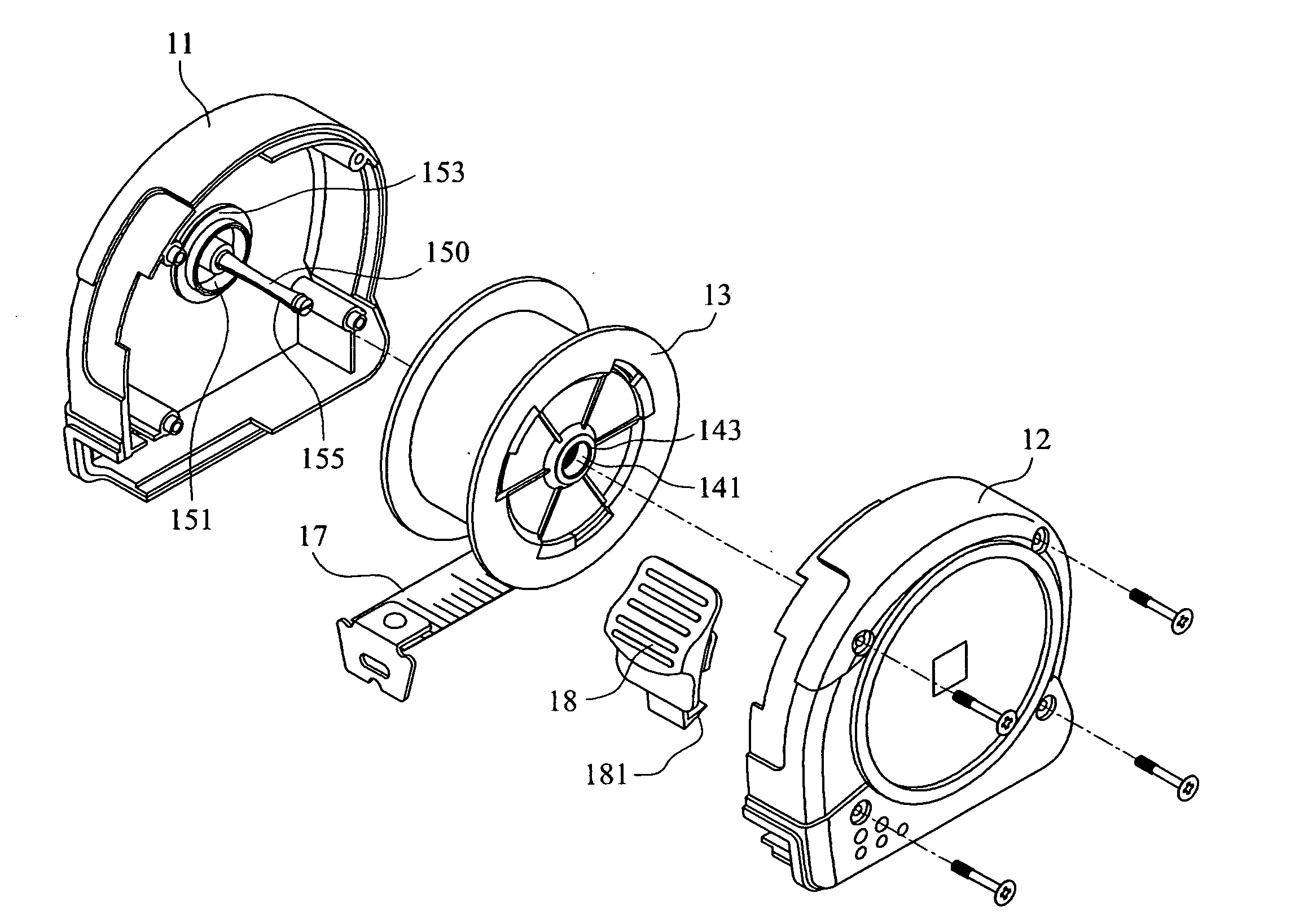
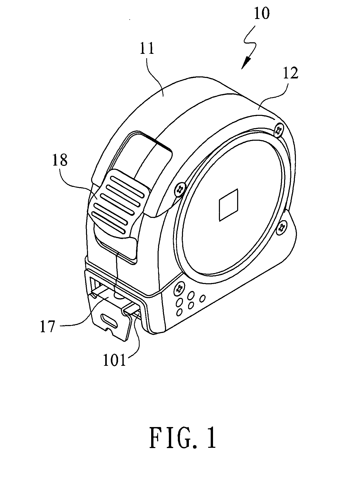
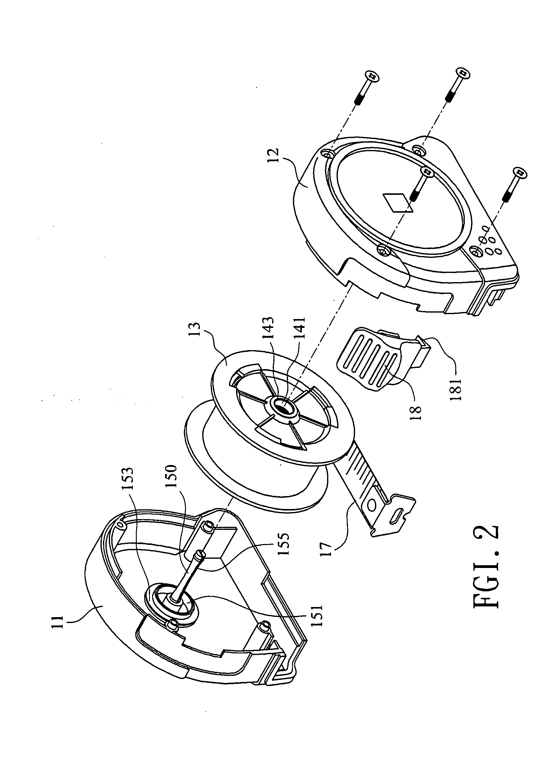
[0015]The present invention relates to an improved tape ruler, as shown in FIG. 1, FIG. 2, FIG. 3, and FIG. 4. The present invention is equipped with one plastic-injected hollow housing 10, which is formed by mounting one left housing 11 and one right housing 12 together. There is one space inside said hollow housing 10 and one roller 13 is placed in said space. Two inwardly protruding axis tubes 141 and 142 are respectively formed on the middle of the left and the right side walls of the roller 13, whereas two supplementary tubes 143 and 144, which are made of materials different from that forming the roller 13, are set on the interior walls of said axis tubes. Two protruding tubes 151 and 152, which match said axis tubes 141 and 142, are respectively formed on the interior walls of the housing 11 and 12. Sleeves 153 and 154, which are made of different materials such as copper and iron, are respectively mounted onto said protruding tubes 153 and 154 (thus said protruding tubes 151...


PUM


Abstract

Disclosed is an improved tape ruler, comprising mainly a hollow housing constructed by two parts (the left and the right) to form a space for other components to place in, a roller of ruler blade placed in said space, two interiorly protruding axis tubes respectively set on the middle of the left and the right parts of the housing, two supplementary tubes of different materials set on the interiors of said axis tubes, two protruding tubes that match said axis tubes, two sleeves of different materials further mounted onto said protruding tubes. Said protruding tubes are respectively coupled up with said two axis tubes, allowing the roller to rotate in said space. One rolling spring is placed inside said roller, with one end of it reaching out from an arsis post that extends from the housing inside one of said protruding tubes, and the other end connected with the end of said ruler blade. There is also one other strip-shaped exit formed the tip of the tape. By reducing rotational friction between said axis tubes and the protruding tubes which are set on the interiors of the right and the left half-housings, the resistance force of said tape ruler is greatly alleviated, the length of said spring that pulls the ruler blade out is greatly shortened, and it is therefore more suitable for the use of tape ruler with wider ruler blades.

Description

BACKGROUND OF THE INVENTION[0001]1. Field of the Invention[0002]The present invention relates to an improved tape ruler, especially to an advanced tape ruler that has sleeves mounted onto protruding tubes formed on the interior walls of its right and left parts of housing, as well as supplementary tubes set on the axis tubes of its roller. Then the rotational frictions between said protruding tubes and axis tubes can be greatly reduced, the length of spring that pulls the tape out then can be shortened, and makes it more suitable for wider ruler blades.[0003]2. Description of the Prior Art[0004]Traditional tape rulers comprise of a housing in which there is a space inside to place ruler blade and a roller. One roller is placed within said space, whereas one axis is set on the interior wall of the housing. Said roller is set on the axis and is able to roll within the space. One rolling spring is set in said roller; one end of said spring is connected with the axis, whereas the other ...

Claims


Application Information

Patent Timeline
Patent Type & Authority Applications(United States)
IPC IPC(8): G01B3/10
CPCG01B2003/1043G01B3/1041G01B3/1043
Inventor HUANG, JASON
Owner INDEX MEASURING TAPE
Why Eureka
Eureka Blog
Learn More