Eureka AIR delivers breakthrough ideas for toughest innovation challenges, trusted by R&D personnel around the world.

Connector housing and wire harness

a technology of connecting wires and housings, applied in the direction of couplings/cases, coupling device connections, electrical devices, etc., can solve the problems of reducing the sealing performance of the sealing element which is not desirable, and achieve the reduction of resistance force, reduce resistance force, and improve the operability of assembly

Inactive Publication Date: 2022-03-10
YAZAKI CORP
View PDF0 Cites 0 Cited by
  • Summary
  • Abstract
  • Description
  • Claims
  • Application Information

AI Technical Summary

Benefits of technology

The present invention provides a connector housing and wire harness that can improve operability while maintaining sealing performance when bending the electric wire section of a terminal-equipped electric wire. The connector housing has a larger opening area than the radial cross section area of the electric wire section, reducing resistance force. A protrusion is provided in the inner circumferential surface of the passage hole, suppressing tilting of the electric wire section in the passage hole and in the sealing through hole, reducing the risk of an inhomogeneous contact with the electric wire section. These improvements lead to improved operability for assembling the wire harness. The wire harness includes an improved connector housing and provides sealing performance while ensuring operability.

Problems solved by technology

Such an inhomogeneous tight contact for the sealing through hole may result in reduction of a sealing performance of the seal element which is not desirable.

Method used


Image

  • Connector housing and wire harness
  • Connector housing and wire harness
  • Connector housing and wire harness

Examples


first embodiment

[0025]Hereinafter, embodiments for a connector housing and a wire harness will be described. First, a first embodiment will be described.

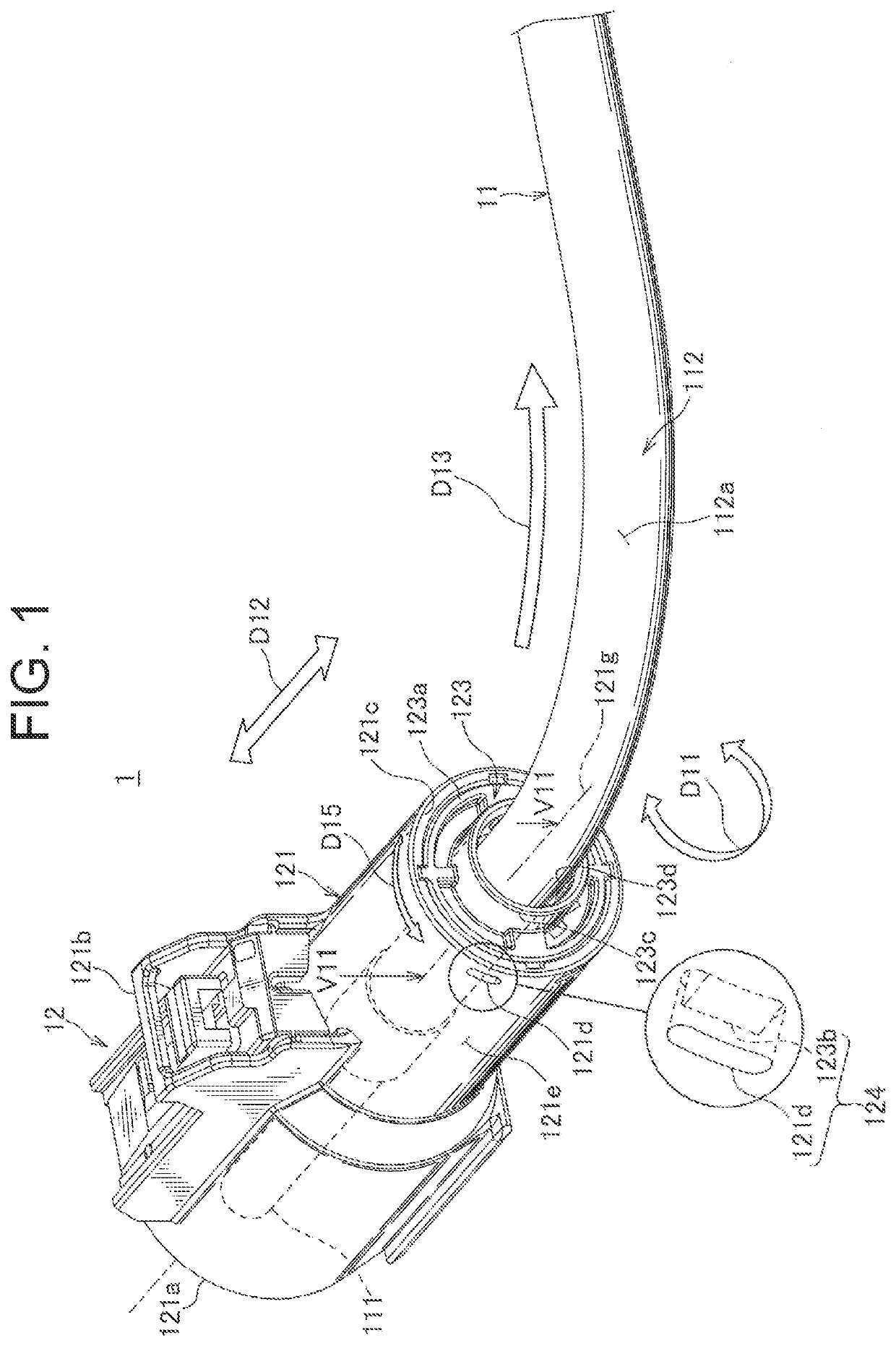
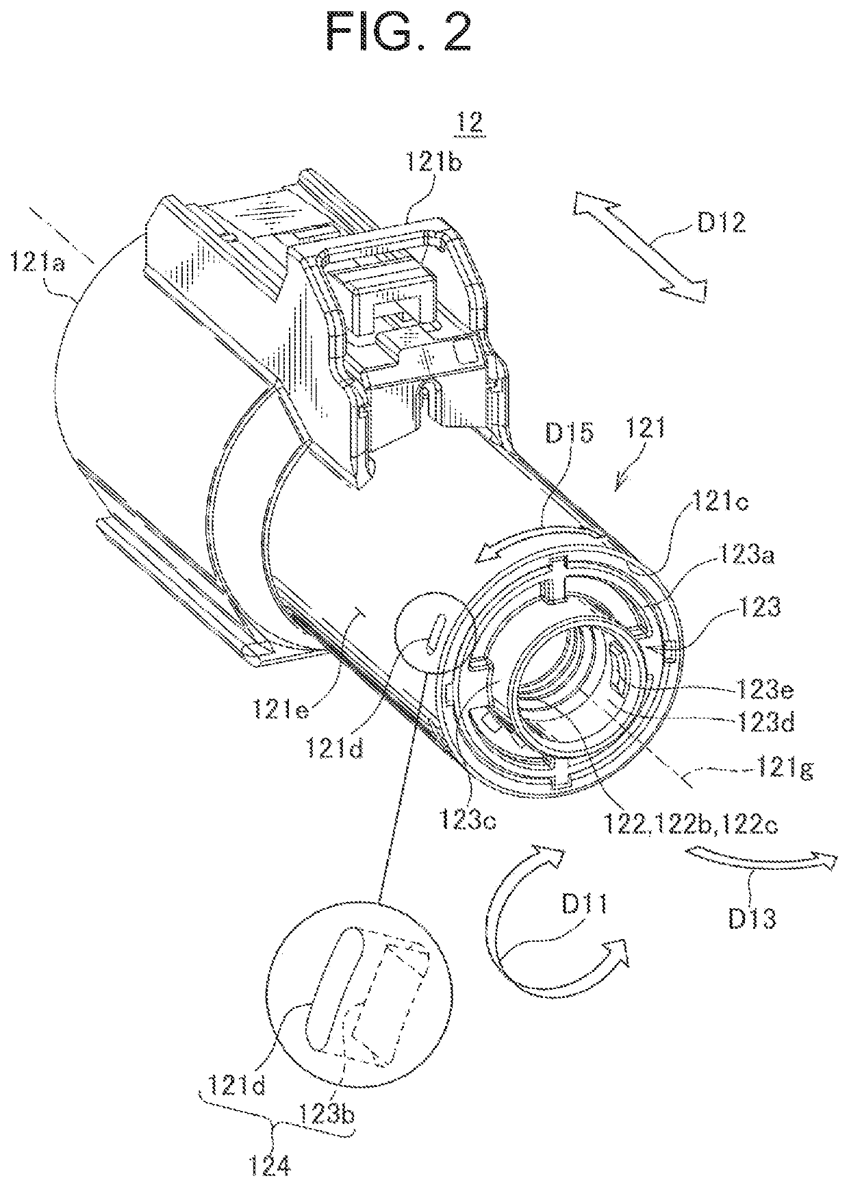
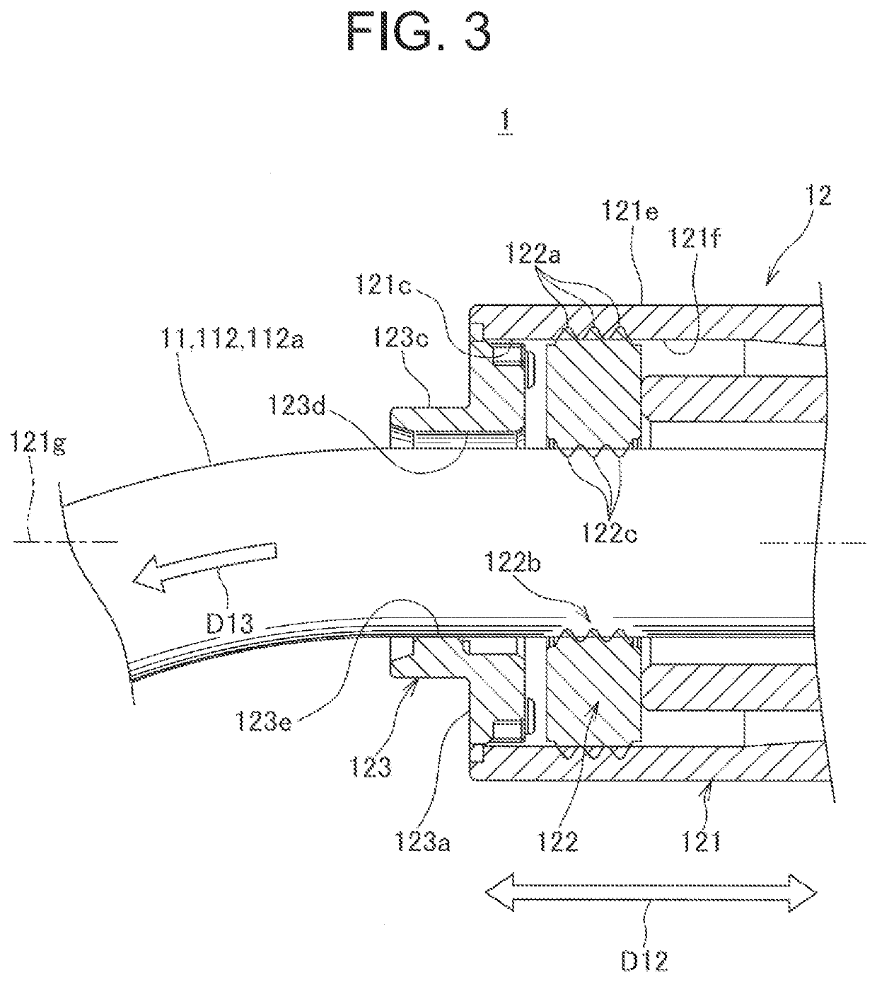
[0026]FIG. 1 shows a perspective view of a wire harness according to a first embodiment. FIG. 2 shows perspective view of a connector housing of the wire harness according to FIG. 1 with a terminal-equipped electric wire removed. FIG. 3 shows a partial sectional view of the wire harness according to FIG. 1 along the line V11-V11 in FIG. 1.

[0027]A wire harness 1 as shown in these FIGS. 1 to 3 is provided for arrangement at a location which may be subject to liquid splashing such as water, e.g. wiring under a bottom of an automobile. The wire harness 1 according to the present embodiment is configured as a single-pole wire harness, and includes one terminal-equipped electric wire 11 and a connector housing 12.

[0028]The terminal-equipped electric wires 11 includes a male connector terminal 111 connected to an end of an electric wire section 112, the c...

second embodiment

[0045]FIG. 5 shows a perspective view of a wire harness according to a FIG. 6 shows a perspective view of a connector housing of the wire harness according to FIG. 5 with a terminal-equipped electric wire removed. Further, FIG. 7 shows a partial sectional view of the wire harness according to FIG. 5 along the line V21-V21 in FIG. 5.

[0046]Similarly to the wire harness 1 according to the first embodiment, a wire harness 2 as shown in these FIGS. 5 to 7 is provided for arrangement at a location which may be subject to liquid splashing such as water, e.g. wiring under a bottom of an automobile. However, the wire harness 2 according to the present embodiment is configured as a two-pole wire harness, and includes two terminal-equipped electric wires 21 and a connector housing 22.

[0047]Each of the terminal-equipped electric wires 21 includes a female connector terminal 211 connected to an end of an electric wire section 212, the connector terminal 211 having a receptacle shape, wherein th...

third embodiment

[0065] as shown in FIG. 9, a rear holder 323 has two passage holes 323d for electric wire sections 212, wherein the two passage holes 323d are not circular holes, but elongate holes which are shown as being oriented horizontally in this Figure. The passage holes 323d having an elongate hole shape has a short axis dimension in a plan view which coincides with a diameter of the electric wire section 212 or is slightly larger. On the other hand, the passage holes 323d have a long axis dimension which is significantly larger than the diameter of the electric wire section 212. Due to the elongate hole shape with such dimensions, the passage holes 323d are configured as through holes which have a larger opening area than a radial cross section area of the electric wire sections. These passage holes 323d having such an elongate hole shape are further arranged coaxially with the sealing through holes 222b. Furthermore, a protrusion 323e is provided on an arc section of an inner circumferent...


PUM


Abstract

A connector housing includes a housing main body, a seal element configured to tightly seal a gap between an outer circumferential surface of an electric wire section of a terminal-equipped electric wire and an inner circumferential surface of the housing main body, and a rear holder which is a lid element configured to be attached to the housing main body so as to close the rear side opening and has a passage hole and a protrusion, the passage hole allowing the electric wire section to pass therethrough and having a larger opening area than a radial cross section area of the electric wire section, wherein the protrusion protrudes from a portion of an inner circumferential surface of the passage hole in a circumferential direction with a protrusion length, the protrusion length being adapted to an inner circumference position of a sealing through hole.

Description

BACKGROUND OF THE INVENTIONTechnical Field[0001]The present invention relates to a connector housing configured to accommodate a connector terminal of a terminal-equipped electric wire, and a wire harness with such a connector housing.Background Art[0002]For example, a wire harness may be intended to be arranged at a location which may be subject to liquid splashing such as water, such as wiring under a bottom of an automobile. Conventionally, many of wire harnesses to be arranged at such a location have a structure for suppressing liquid entering the inside of a connector housing, the connector housing being provided at an end of the wire harness. In such a connector housing, an electric wire section of a terminal-equipped electric wire with a connector terminal accommodated therein may extend to the outside at a rear side of the connector housing, wherein this rear side tends to be weakened with regard to liquid entering the inside. Here, the connector housing often has a structur...

Claims


Application Information

Patent Timeline
Patent Type & Authority Applications(United States)
IPC IPC(8): H01R13/52
CPCH01R13/5205H01R2201/26H01R13/5208H01R13/562
Inventor SATO, TAKAHIKOKONO, SHIN
Owner YAZAKI CORP
Why Eureka
Eureka Blog
Learn More