Printing apparatus

a technology of printing apparatus and printing plate, which is applied in the direction of printing, typewriters, other printing apparatus, etc., can solve the problems of waiting periods and reducing and achieve the effect of improving the work efficiency of operators and less waiting periods

Active Publication Date: 2009-09-24
BROTHER KOGYO KK
View PDF6 Cites 1 Cited by
  • Summary
  • Abstract
  • Description
  • Claims
  • Application Information

AI Technical Summary

Benefits of technology

[0009]In view of the above, the present invention is advantageous in that a printing apparatus capable of printing images successively with less waiting periods for an operator so that work efficiency of the operator is improved, is provided.
[0011]With the printing apparatus according to the above configuration, the second printing operation can be reserved so that the second printing operation can be started efficiently after completion of the first printing process or during the first printing process. Thus, the operator is not required to stand by the printing apparatus and await the first printing process to be completed, and operation efficiency of the operator can be improved.

Problems solved by technology

Therefore, the waiting periods to reduce work efficiency of the operator are caused.

Method used


Image

  • Printing apparatus
  • Printing apparatus
  • Printing apparatus

Examples


Embodiment Construction

[0024]Hereinafter, an embodiment according to an aspect of the present invention will be described with reference to the accompanying drawings.

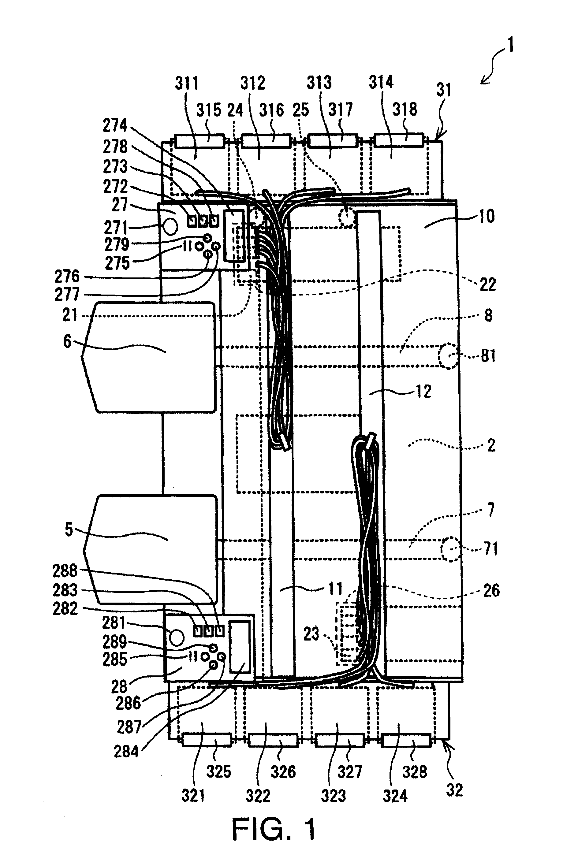
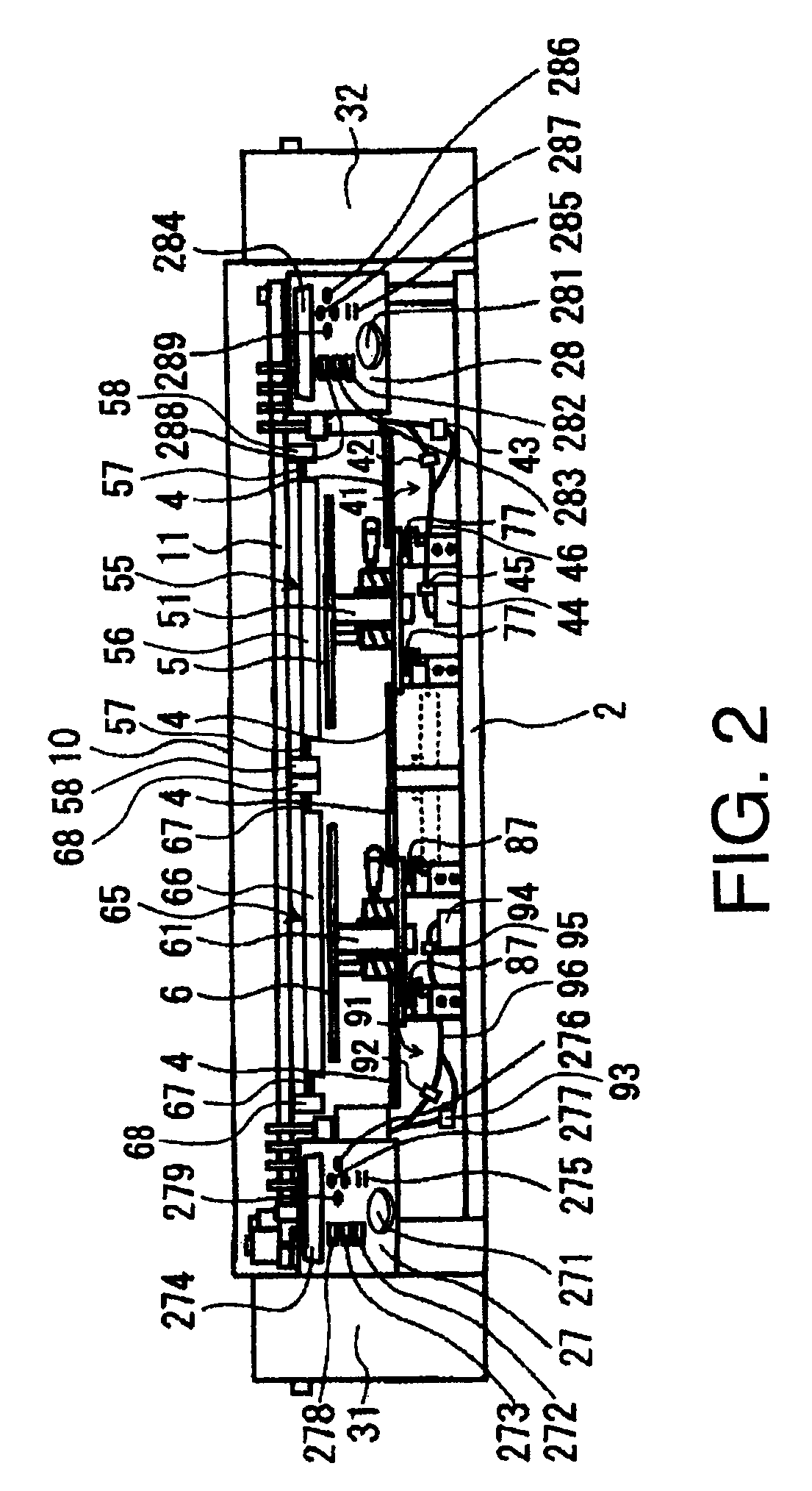
[0025]An inkjet printer 1 according to the embodiment of the present invention will be described with reference to FIGS. 1 through 3. FIG. 1 is a top plane view of the inkjet printer 1 according to the embodiment of the present invention. FIG. 2 is a front view of the inkjet printer 1 according to the embodiment of the present invention. FIG. 3 is a block diagram to illustrate an electrical configuration of the inkjet printer 1 according to the embodiment of the present invention.

[0026]The inkjet printer 1 according to the present embodiment is an inkjet printer having a first print head 23 to eject opaque white (W) ink onto a recording medium and a second print head 21, from which inks in colors of cyan (C), magenta (M), yellow (Y), and black (K) are ejected onto the recording medium. The recording medium in the present embodiment is a piece...


PUM


Abstract

A printing apparatus, having at least two platens, at least one print head, at least one print head drive unit to drive the print head in a main scanning direction, at least two platen drive units to drive the platens in an auxiliary direction, at least one ink cartridge, at least two operation input units to be operated by an operator to instruct the printing apparatus to activate a first printing process and a second printing process respectively, and a cooperation controller system to control the print head, the print head drive unit, the first platen drive unit, and the second platen drive unit to behave in cooperation with one another so that the second printing process is started one of after and during the first printing process when an instruction to start the second printing process is entered whilst the first printing process is in progress, is provided.

Description

CROSS REFERENCE TO RELATED APPLICATION[0001]This application claims priority from Japanese Patent Application No. 2008-075698, filed on Mar. 24, 2008, the entire subject matter of which is incorporated herein by reference.BACKGROUND[0002]1. Technical Field[0003]An aspect of the present invention relates to a printing apparatus, more specifically, a printing apparatus to print images on fabrics.[0004]2. Related Art[0005]Conventionally, a printing apparatus for printing an image on a piece of fabric, having a platen to hold the fabric, a print head to eject inks onto the fabric, a carriage to move the print head, an operation plane, and a set of colored inks, has been known. Such a printing apparatus is disclosed in, for example, Japanese Patent Provisional Publication No. 2004-268506. According to the printing apparatus, an image represented by a piece of print data is formed on a piece of fabric as the carriage is moved in a main scanning direction and the platen is moved in an auxi...

Claims


Application Information

Patent Timeline
Patent Type & Authority Applications(United States)
IPC IPC(8): B41J29/38
CPCB41J3/4078B41J2/2117B41J11/06B41J3/543
Inventor KAYANAKA, YOSHIHISA
Owner BROTHER KOGYO KK
Why Eureka
Try Eureka