Eureka AIR delivers breakthrough ideas for toughest innovation challenges, trusted by R&D personnel around the world.

Method and apparatus for drying

Inactive Publication Date: 2009-10-01
FUJIFILM CORP
View PDF6 Cites 13 Cited by
  • Summary
  • Abstract
  • Description
  • Claims
  • Application Information

AI Technical Summary

Benefits of technology

[0027]According to the present invention, exhaust discharge is carried out at farther upstream and downstream sides from the windshield plates disposed at upstream and downs

Problems solved by technology

However, when a drying box with a shape corresponding to W/L≧1 is used, there arises a problem that unevenness in drying becomes very easy to occur in a width direction of the web.
Therefore, when W/L≧1,

Method used


Image

  • Method and apparatus for drying
  • Method and apparatus for drying
  • Method and apparatus for drying

Examples


Example

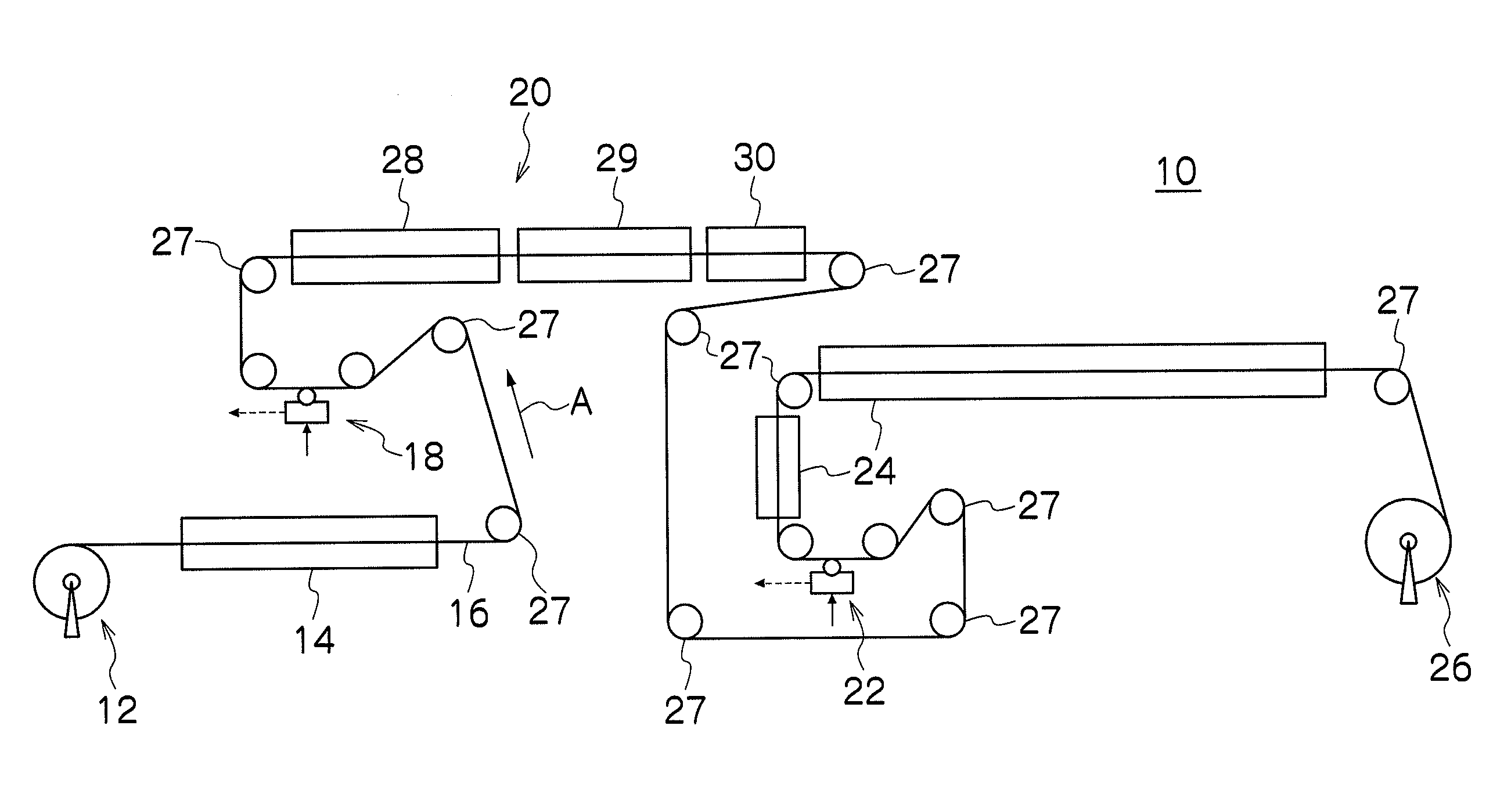
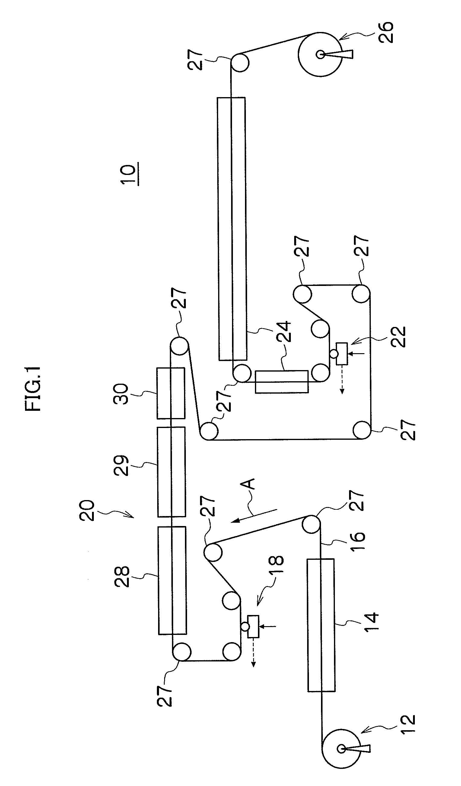
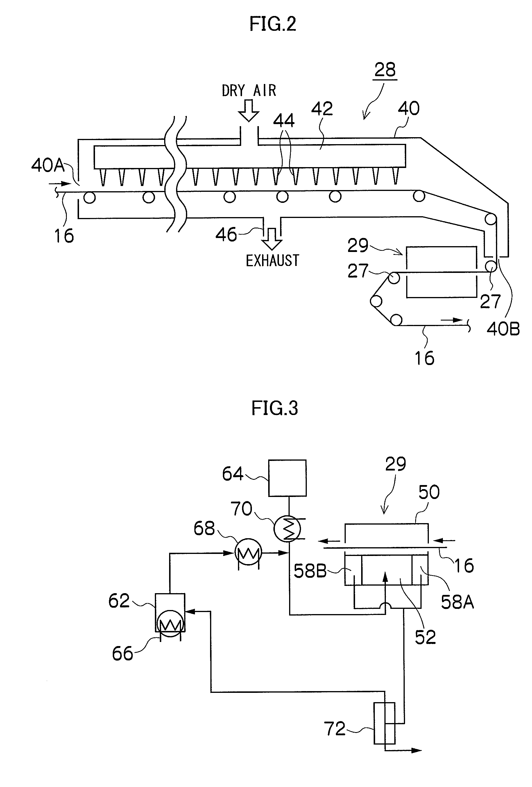
[0301]Further, as the vapor atmosphere drying section, in Example 1 was used one with a configuration illustrated in FIG. 4 and in Example 2 was used one with a configuration shown in FIG. 7 (the support roller was a metal roller of φ75 mm). Furthermore, in Comparative Example 1, a drying section with a configuration illustrated in FIG. 6 was used.

Example

[0302]In the tests of Examples 1, 2, and Comparative Example 1, the coating liquid was coated on the aluminum web by a coating machine and, thereafter, the web was conveyed through a hot air drying section using dry air and dried for 30 seconds. As a result, the coated film reaches a drying point and solidifies. This is thereafter conveyed continuously to the vapor atmosphere drying sections of Examples 1, 2, and Comparative Example 1, and was dried under a steam atmosphere for 0.8 second. Thereafter, a piece was cut out from the wound web and the amount of residual γ-butyrolactone (γ-BL) remaining in the film was measured by gas chromatography at seven points in the width direction to examine residual distribution in the width direction. The results of measurement are shown in Table 1. In Table 1, the positions on the aluminum web are shown with the center of the web set as the standard (0 mm), and a position right to this is denoted by a plus sign and the left side by a minus sign...


PUM


Abstract

A method for drying a material to be dried, the material containing a first solvent and being conveyed, comprising the steps of:
    • supplying hot air from a supply unit to the material, the hot air containing vapor of a second solvent having a smaller or equal molecular volume than the molecular volume of the first solvent,
    • wherein exhaust is discharged at farther upstream and farther downstream portions from windshield plates disposed at upstream and downstream of the supply unit, in the direction of conveying the material to be dried.

Description

BACKGROUND OF THE INVENTION[0001]1. Field of the Invention[0002]The present invention relates to a method and apparatus for drying, especially to a method and apparatus for drying employed in the manufacturing process of lithographic printing plates.[0003]2. Description of the Related Art[0004]Lithographic printing plate, various optical films, silver halide films, photographic papers, and magnetic recording materials such as base films for video tapes and the like are manufactured by applying coating liquids such as a photosensitive layer forming liquid, a thermosensitive layer forming liquid, a photosensitive emulsion, a magnetic layer forming liquid, and the like on belt-like materials such as a support web, a base film, baryta paper, and the like, the belt-like material being moved in one direction, followed by drying, and, if necessary, cutting into a predetermined size. In this manufacturing process, drying and removing solvents contained in the coating liquids with high accur...

Claims


Application Information

Patent Timeline
IPC IPC(8): F26B7/00F26B25/20
CPCF26B13/10F26B21/14F26B21/004
Inventor TAGUCHI, TAKAOHAYASHI, KENJI
Owner FUJIFILM CORP
Why Eureka
Eureka Blog
Learn More