
Internal assembly for a faucet

a technology for internal assembly and faucets, which is applied in the direction of water supply installation, transportation and packaging, mechanical equipment, etc., can solve the problems of compromising durability and installation of cartridges, affecting the performance of conventional single-handle water faucets, and affecting the durability and cost of manufactur

Inactive Publication Date: 2009-10-01
XIAMEN LOTA INT CO LTD
View PDF27 Cites 17 Cited by
  • Summary
  • Abstract
  • Description
  • Claims
  • Application Information

AI Technical Summary

Benefits of technology

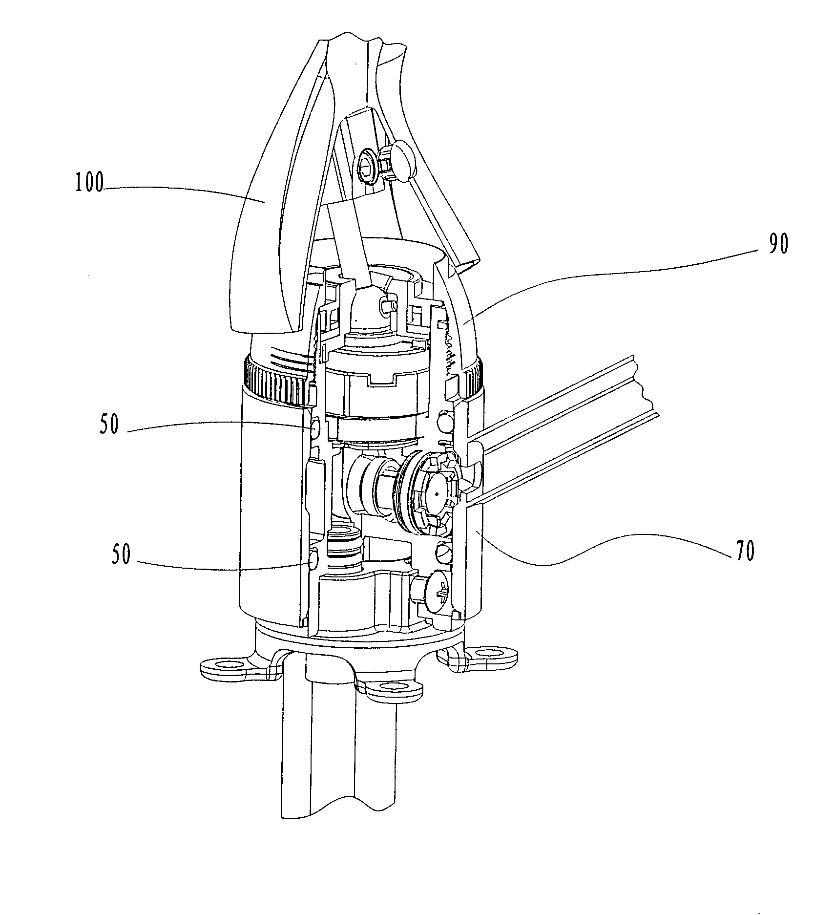
[0010]The joystick has a depending actuator that is received in the central aperture of the upper disk that operably connects it to the upper disk. Actuation of the joystick results in movement of the upper disk and intermediate disk, varying the position of the mixing cavity relative to the hot and cold water inlets.

Problems solved by technology

Conventional single-handle water faucets suffer from a number of limitations that negatively affect their performance, durability and cost of manufacture.
As a result, the discharge line in such faucets assumes an unnecessarily long and circuitous path to the spout that compromises durability and installation of the cartridge in the faucet body.
Another disadvantage of conventional water faucets and mixing valves or cartridges is that water lines must be disconnected before the main body of the faucet may be removed for maintenance or replacement.

Method used


Image

  • Internal assembly for a faucet
  • Internal assembly for a faucet
  • Internal assembly for a faucet

Examples


Embodiment Construction

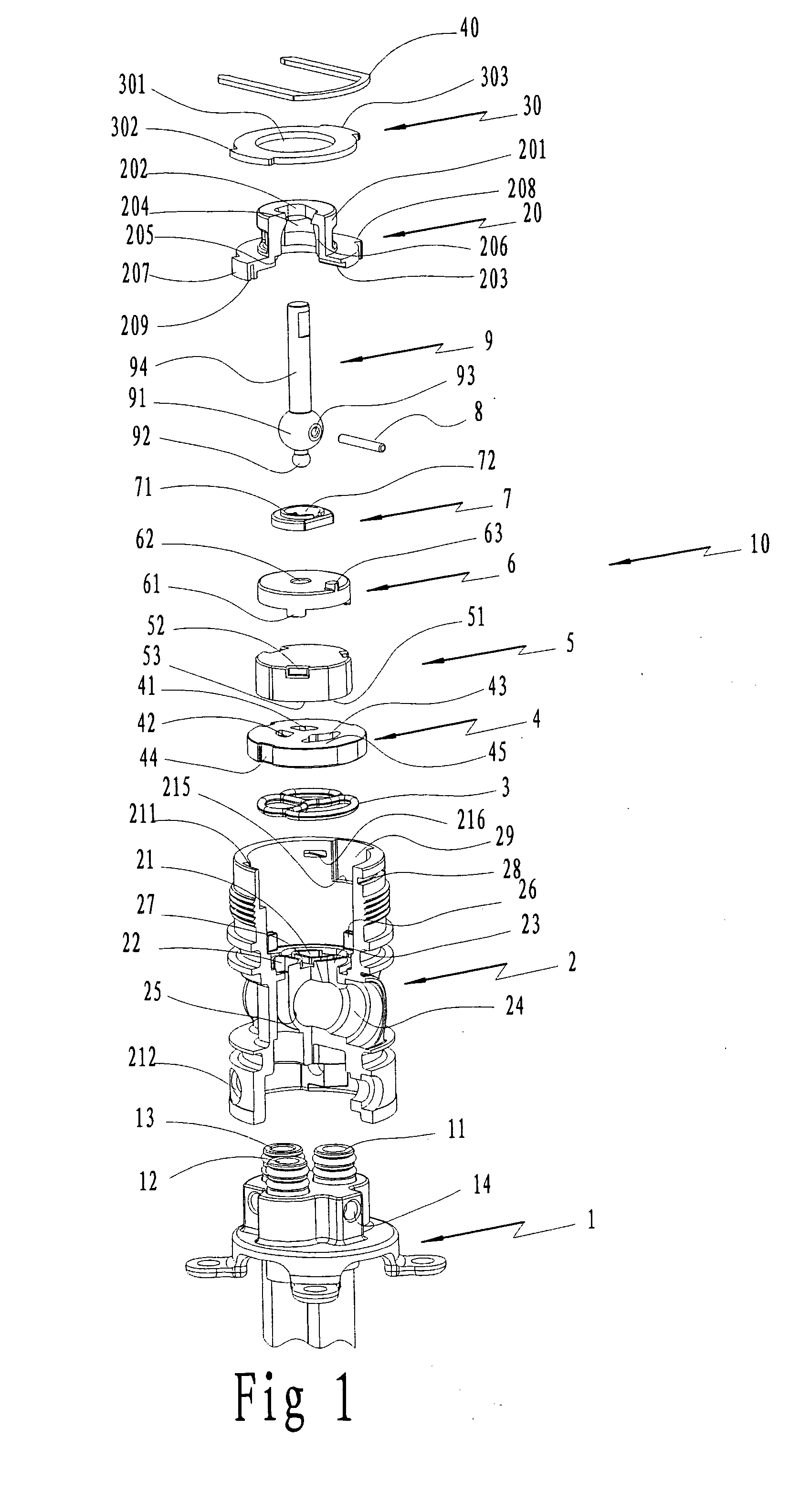
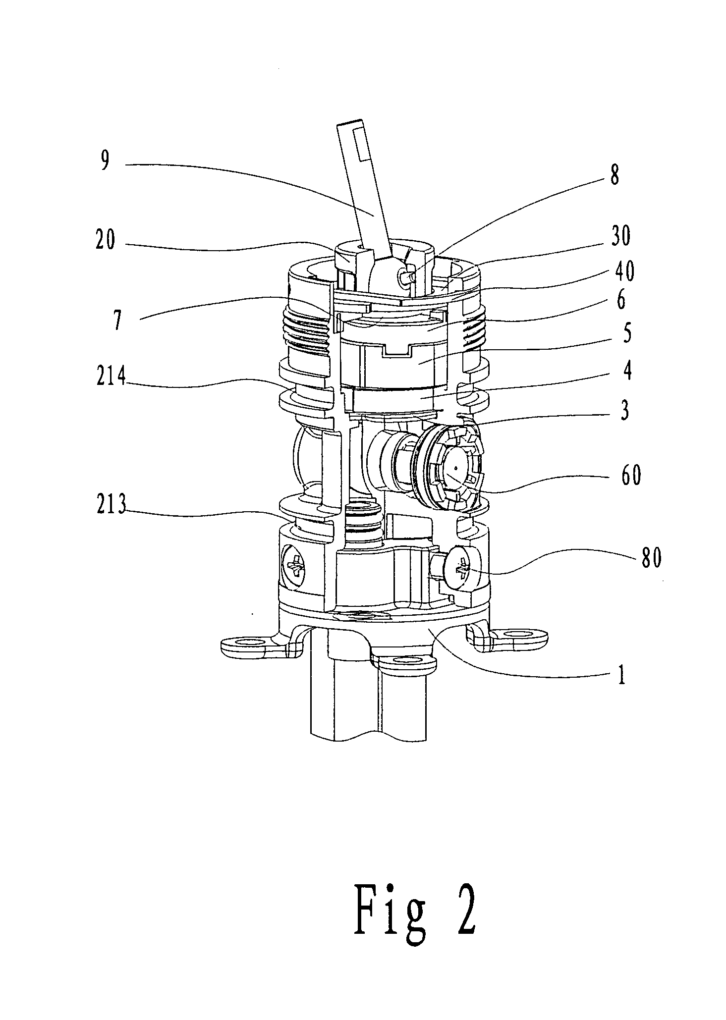
[0019]FIG. 1 depicts one embodiment of an internal assembly 10 for a faucet of the present invention. The internal assembly 10 includes an independent base 1, a main body 2, a sealing element 3, a lower disk 4, an intermediate disk 5, an upper disk 6, a fixing element 7, a post 8, a joystick 9, a seat 20, an annulus 30, and a retaining U-ring 40.

[0020]A cold water inlet 11, a hot water inlet 12 and a water discharge line 13 may be connected to the independent base 1. The sidewall of independent base 1 includes at least one screw hole 14.

[0021]The main body 2 includes a cold water inlet hole 21, a hot water inlet hole 22, a mixed water outlet hole 23, a spout discharge hole 25, and optionally, a hole 24 for installing a change valve 60.

[0022]The inner wall of the main body 2 includes projections 26. A groove 27 is located around the cold water inlet hole 21, hot water inlet hole 22, and mixed water outlet hole 23. Groove 27 receives sealing element 3.

[0023]The top wall of the main bo...


PUM


Abstract

The invention is an internal assembly for a faucet comprising an independent base portion; a main body portion; a sealing element; at least one discharge element; a handle that an operator actuates to deliver water at a desired temperature through the discharge element; an annulus, and a radial seal. The main body portion includes a lower disk. The lower disk has a cold water inlet, a hot water inlet and a mixed water outlet. An intermediate disk is positioned adjacent the lower disk. The intermediate disk has a recessed mixing cavity, and further has a dual lobe sealing element to provide the mixing cavity with an arcuate configuration. An upper disk is positioned adjacent to the intermediate disk, and has a central aperture and at least one engaging member that operably couples the upper disk to the intermediate disk. A seat is positioned adjacent the upper disk, and the seat has a central opening. A post and a fixing element, including a flange and an opening, receive a portion of the actuator ball of a joystick, and facilitate operable connection of the joystick with the upper disk. A joystick having a shaft extends through the seat opening, and through the main body. The joystick has a depending actuator that is received in the upper disk aperture to operably connect the joystick to the upper disk. Actuation of the joystick results in movement of the upper disk and intermediate disk, to vary the position of the mixing cavity relative to the hot and cold water inlets.

Description

CROSS-REFERENCE TO RELATED APPLICATION[0001]N / AFEDERALLY SPONSORED RESEARCH OR DEVELOPMENT[0002]N / AFIELD OF THE INVENTION[0003]The invention relates to an internal assembly for a faucet in which mixed water may discharge directly from the assembly.BACKGROUND OF THE INVENTION[0004]Single handle water faucets suitable for commercial and residential use are well-known. These faucets typically include, for example, a base plate, an upwardly extending main body portion, a discharge segment or spout, and a centrally located handle. A mixing valve or cartridge is positioned within the main body, and includes a vertically extending joystick that is operably connected to the handle. A hot water line or conduit is connected to a hot water inlet of the cartridge, and a cold water line or conduit is connected to a cold water inlet of the cartridge. The cartridge also includes a mixed water outlet, and a discharge line extends from the water outlet through the spout to provide mixed water for di...

Claims


Application Information

Patent Timeline
Patent Type & Authority Applications(United States)
IPC IPC(8): E03B1/00
CPCF16K11/0785E03C1/04Y10T137/87579
Inventor XINLU, LANPINGLIANG, WU
Owner XIAMEN LOTA INT CO LTD
Learn More