
Condition assessment system and method

Active Publication Date: 2006-04-06
FLORIDA POWER & LIGHT
View PDF52 Cites 15 Cited by
  • Summary
  • Abstract
  • Description
  • Claims
  • Application Information

AI Technical Summary

Benefits of technology

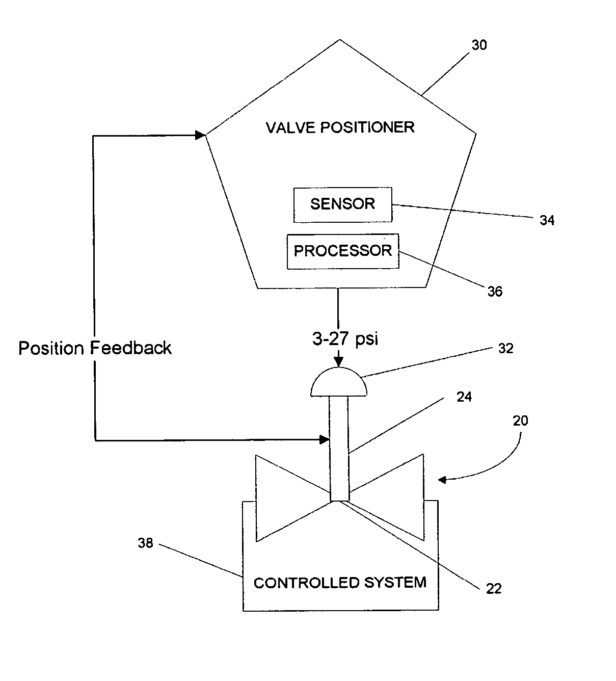
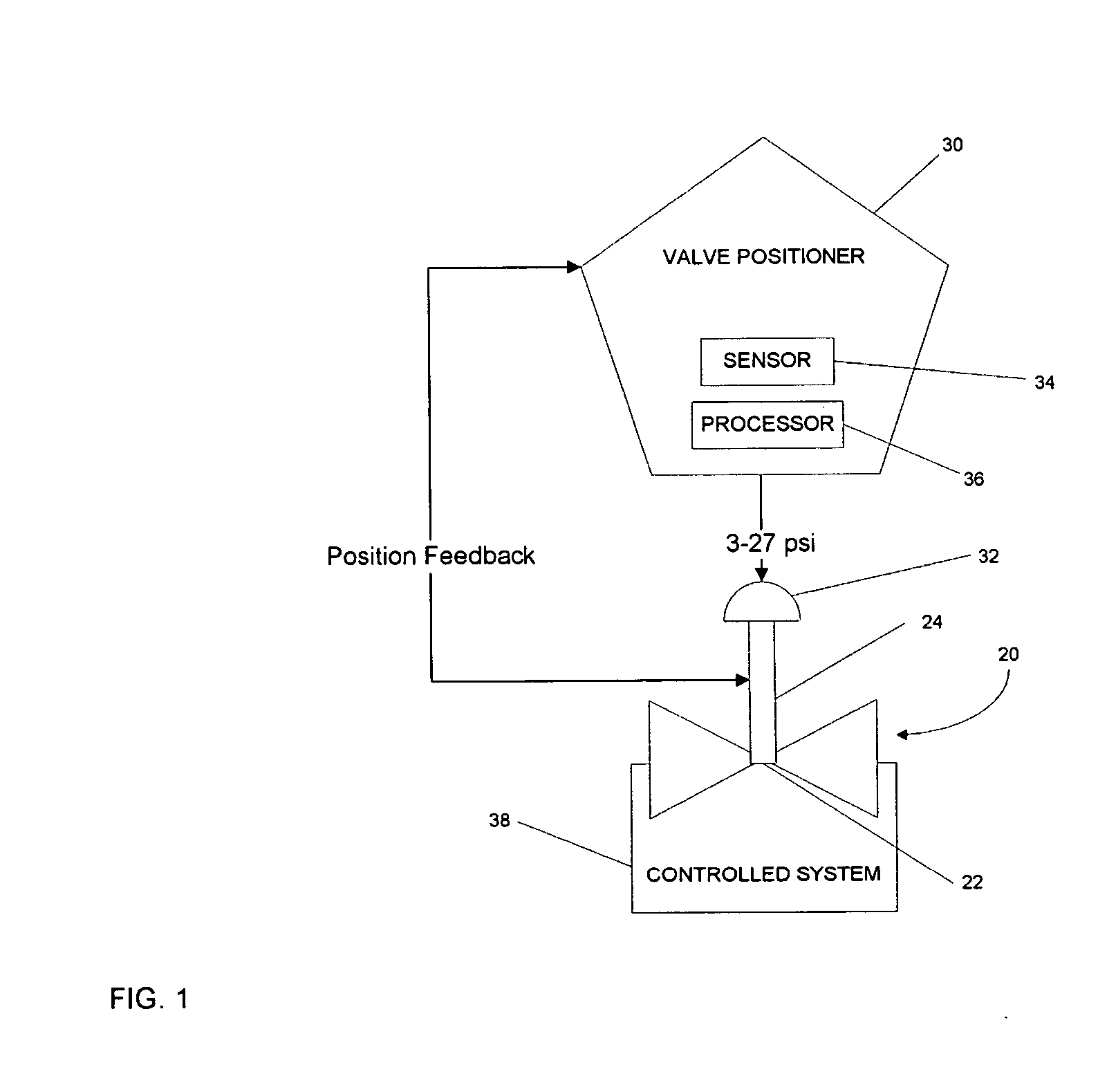
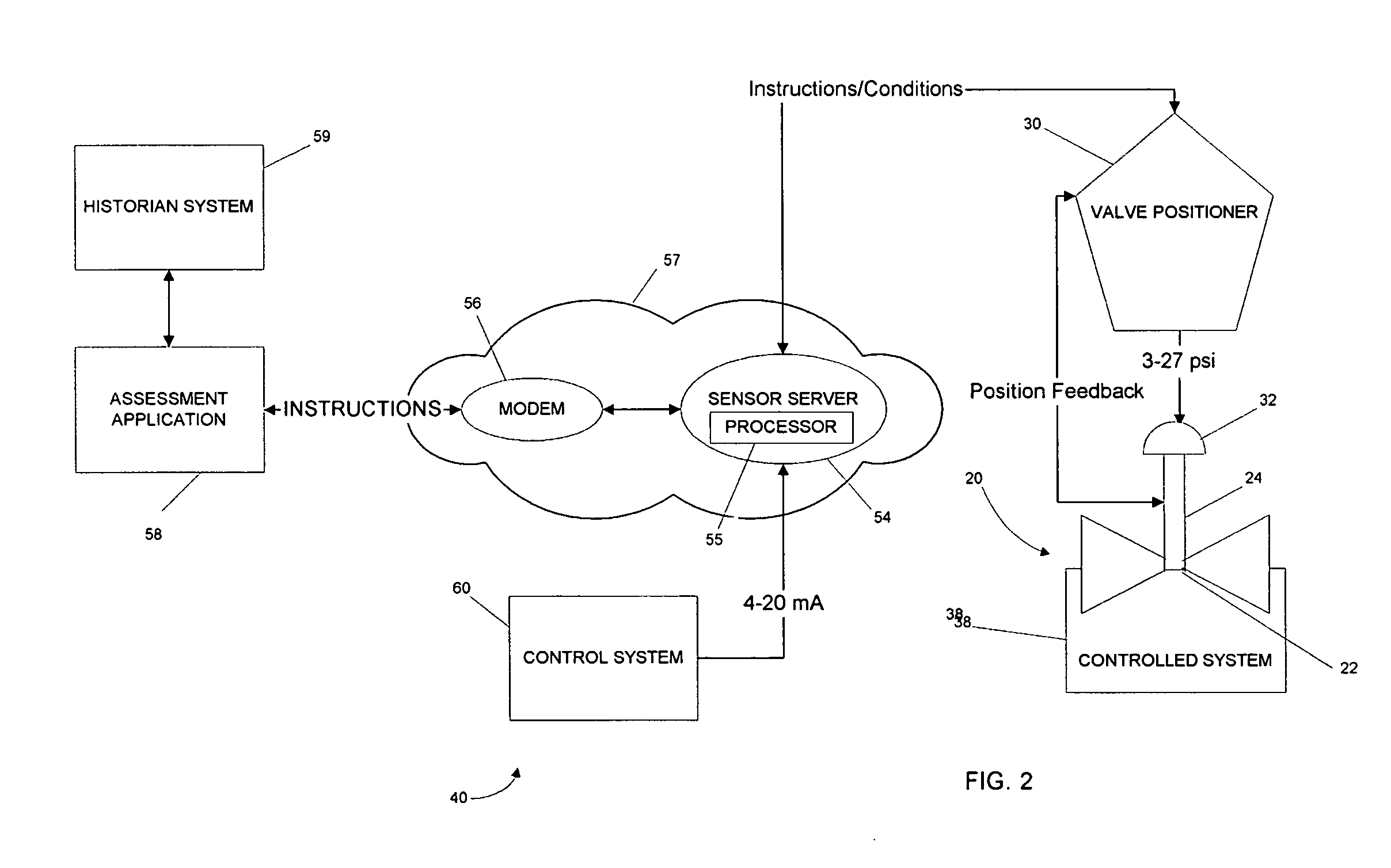
[0003] Embodiments of the invention provide a system for monitoring a condition of a valve. The system can include a valve having a variable position. The system can also include a valve positioner that receives a control instruction, that varies the position of the valve, that determines a condition of the valve, and that transmits the condition. The system can further include a sensor server that receives the condition, that transmits a data stream including the condition, that receives the control instruction from a control system, and that transmits the control instruction to the valve positioner. The system can still further include an assessment application that receives the data stream and t

Problems solved by technology

If one or more components of a manufacturing system fail, the operation of the entire manufacturing system can suffer.
Failing components can cause significant damages or unwanted modifications to the output of the manufacturing system or to other components of the manufacturing system.
In some situations, the damages or modifications can be dangerous.

Method used


Image

  • Condition assessment system and method
  • Condition assessment system and method
  • Condition assessment system and method

Examples


Embodiment Construction

[0008] Before any embodiments of the invention are explained in detail, it is to be understood that the invention is not limited in its application to the details of construction and the arrangement of components set forth in the following description or illustrated in the following drawings. The invention is capable of other embodiments and of being practiced or of being carried out in various ways. Also, it is to be understood that the phraseology and terminology used herein is for the purpose of description and should not be regarded as limited. The use of “including,”“comprising” or “having” and variations thereof herein is meant to encompass the items listed thereafter and equivalents thereof as well as additional items. The terms “mounted,”“connected” and “coupled” are used broadly and encompass both direct and indirect mounting, connecting and coupling. Further, “connected” and “coupled” are not restricted to physical or mechanical connections or couplings, and can include el...


PUM


Abstract

System and method for monitoring and controlling one or more valves. The method can include sensing a condition of a valve, transmitting the condition to a sensor server, and transmitting a data stream including the condition to an assessment application. The method can also include generating a predictive model and comparing the condition to the predictive model. The method can further include transmitting a control instruction to at least one of a valve positioner and the sensor server and varying the position of the valve based on the control instruction.

Description

BACKGROUND OF THE INVENTION [0001] As manufacturing systems become more automated, control mechanisms that monitor and regulate the numerous components, such as controllable valves, become more important and prominent. Many current manufacturing systems employ a large number of control mechanisms that monitor operating parameters, such as flow through valves, to ensure that the system performs as desired. [0002] If one or more components of a manufacturing system fail, the operation of the entire manufacturing system can suffer. Failing components can cause significant damages or unwanted modifications to the output of the manufacturing system or to other components of the manufacturing system. In some situations, the damages or modifications can be dangerous. SUMMARY OF THE INVENTION [0003] Embodiments of the invention provide a system for monitoring a condition of a valve. The system can include a valve having a variable position. The system can also include a valve positioner tha...

Claims


Application Information

Patent Timeline
IPC IPC(8): G08B21/00
CPCG08B25/045G08B31/00F16K37/0083
Inventor SCHULTZ, PAUL C.
Owner FLORIDA POWER & LIGHT
Learn More