Percutaneous heart valve delivery and implantation system enabling fracture of a previously present valve

a delivery system and heart valve technology, applied in the field of percutaneous heart valve delivery system, can solve the problems of further reduction of the valve area, severe compression of the delicate leaflets of the new valve over the enclosing stent, and unfavorable outcom

Active Publication Date: 2021-02-18
RGT UNIV OF CALIFORNIA
View PDF0 Cites 1 Cited by
  • Summary
  • Abstract
  • Description
  • Claims
  • Application Information

AI Technical Summary

Benefits of technology

[0006]In some examples, the percutaneous heart valve delivery system further includes a handle coupled to the valve delivery catheter, wherein the handle includes an adjustment control connected to the first inflatable balloon, wherein the adjustment control is configured to vary a position of the first inflatable balloon in the valve delivery catheter, wherein the first inflatable balloon can be positioned distal, at the same position or proximal in relation to the replacement transcatheter heart valve.
[0007]In some examples, the handle further includes a valve expansion / compression control and a valve release control that is configured to disconnect the replacement transcatheter valve from the valve delivery catheter once the replacement transcatheter heart valve is deployed.

Problems solved by technology

In many instances, patients with previously-implanted surgical prosthetic valve who require transcatheter valve-in-valve (VIV) replacement have higher residual pressure gradients, in which transcatheter valve implantation leads to unfavorable outcome due to patient-prosthetic mismatch, confirmed by further reduction of the valve area and non-optimal expansion of the new transcatheter valve.
However, this technique comes with drawbacks due to the valvular insufficiency that occurs because of the BVF, which needs to be immediately addressed.
However, since the new transcatheter valve is now implanted, inflating a high-pressure balloon inside of the new transcatheter valve to fracture the old ring would lead to severe compression of the new valve's delicate leaflets over its enclosing stents.
This severe pressure on the valve leaflets over the stent can result in leaflet damage and damage the leaflet surface.

Method used


Image

  • Percutaneous heart valve delivery and implantation system enabling fracture of a previously present valve
  • Percutaneous heart valve delivery and implantation system enabling fracture of a previously present valve
  • Percutaneous heart valve delivery and implantation system enabling fracture of a previously present valve

Examples


Embodiment Construction

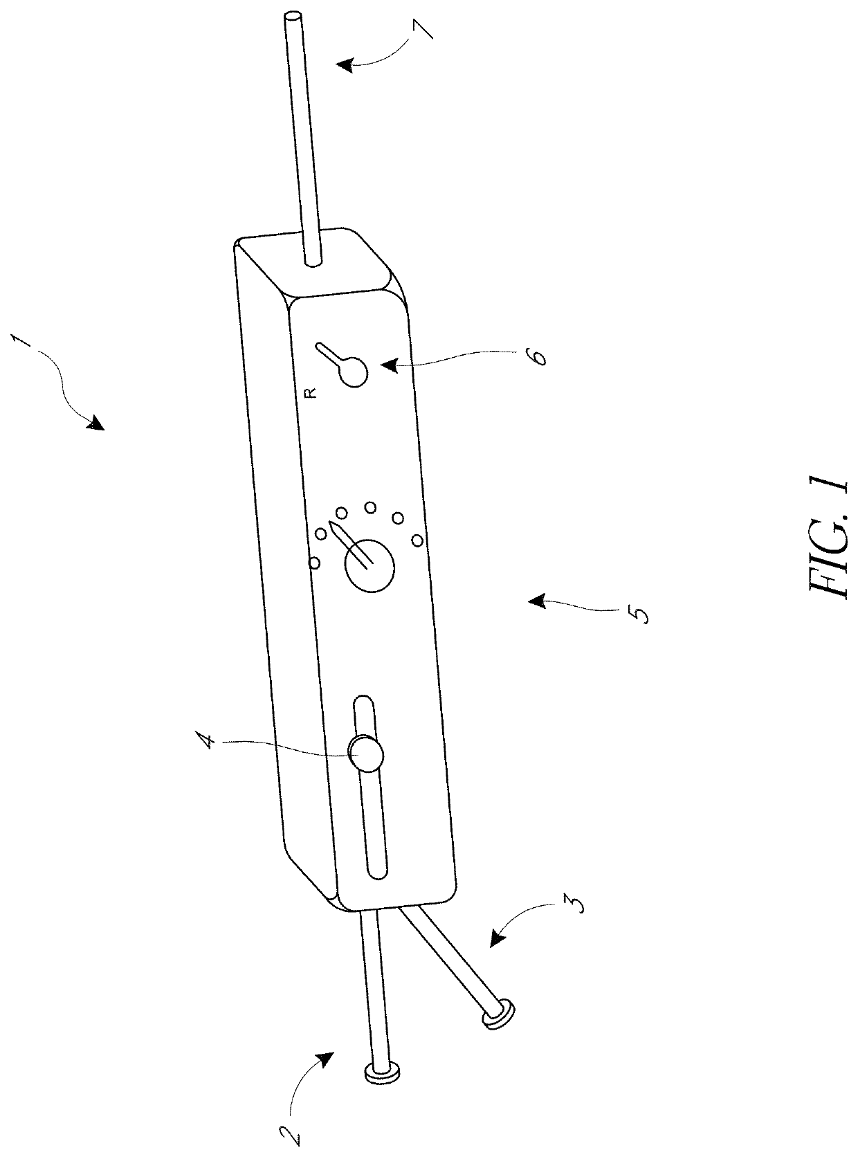
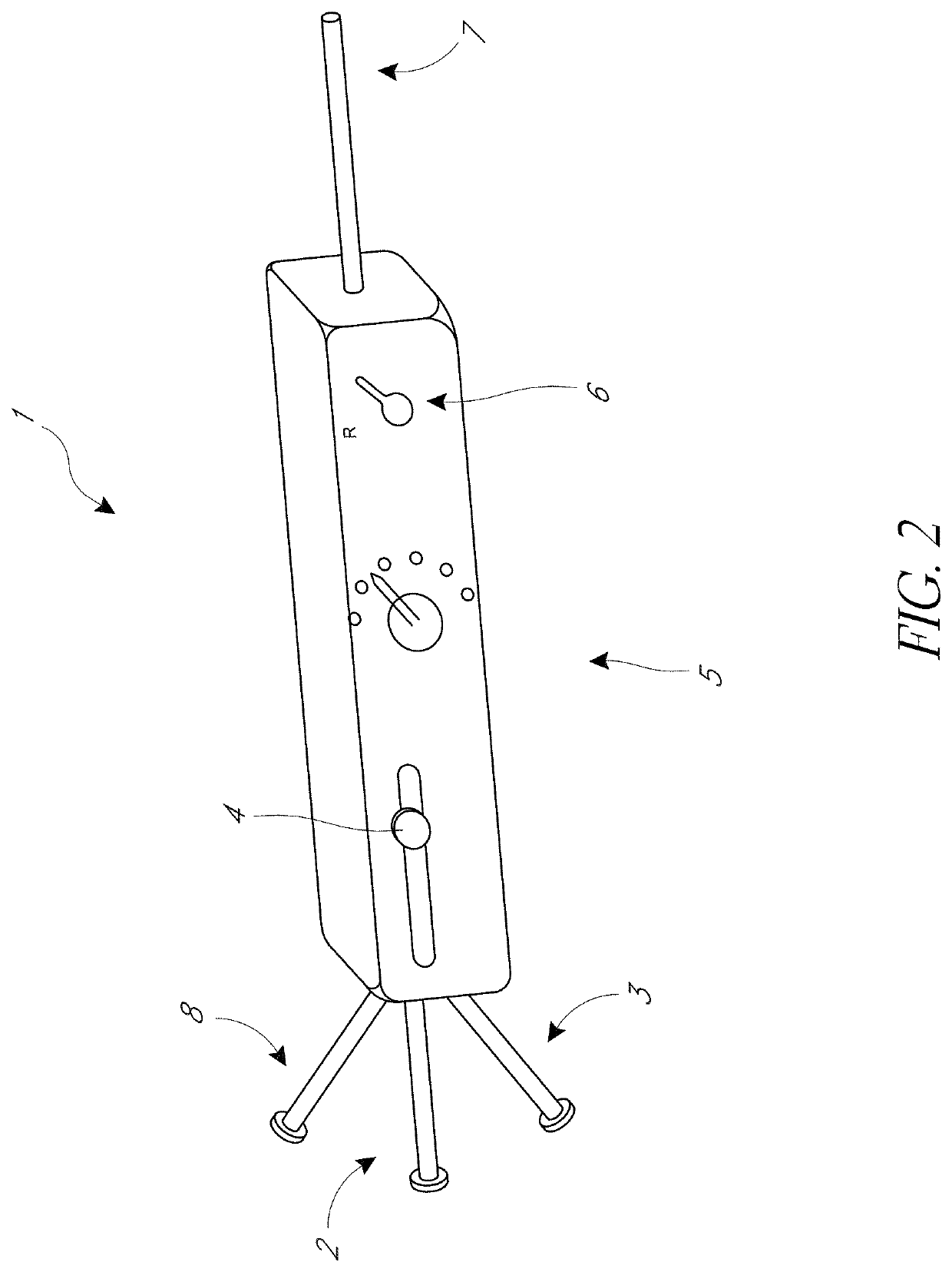
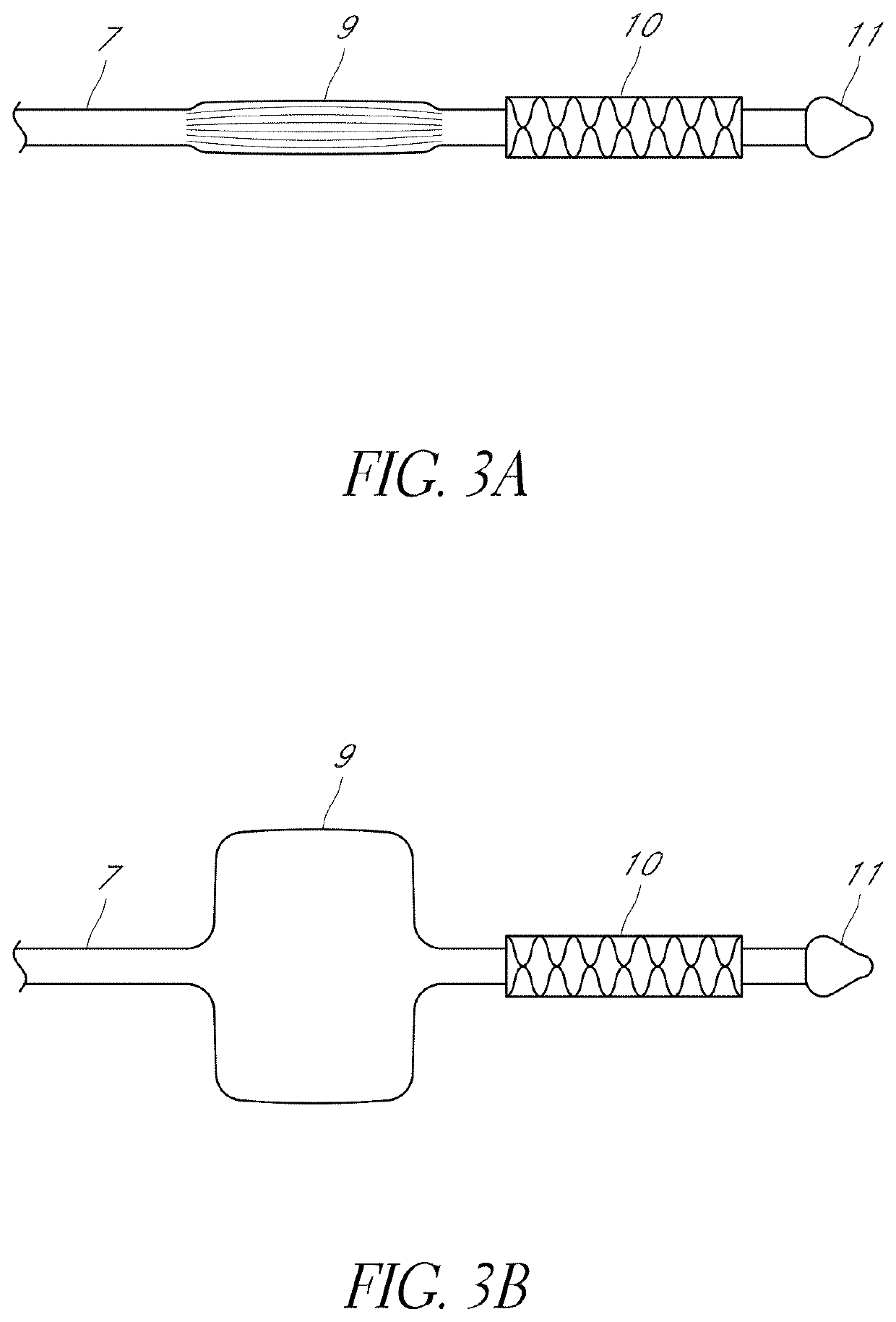
[0052]To mitigate the problems discussed above, we developed a novel percutaneous heart valve delivery system for delivery and implantation of a prosthetic valve that incorporates a balloon. The position of the balloon may be adjustable, and the balloon is used to fracture a previously-implanted prosthetic valve in situ immediately before a new transcatheter valve is implanted, without interfering with the transcatheter valve to be implanted.

[0053]Compared to previous transcatheter delivery systems that require a two-step procedure for replacing a previously implanted prosthetic heart valve in a subject, including the use of (1) a first transcatheter system with a balloon that is used to fracture a previously implanted prosthetic heart valve, followed by withdrawal of the first transcatheter balloon from the subject; and (2) a second transcatheter system that is used to deliver a replacement transcatheter heart valve to the subject, we disclose herein delivery systems that mediate b...


PUM


Abstract

A percutaneous heart valve delivery system including a valve delivery catheter coupled with a first inflatable balloon positioned at a distal end of the valve delivery catheter, wherein the first inflatable balloon is configured to fracture a previously implanted prosthetic heart valve; and a replacement transcatheter heart valve positioned proximal to the first inflatable balloon, wherein the replacement transcatheter heart valve is configured to be implanted subsequently within the previously implanted, fractured prosthetic heart valve, following fracture of the previously implanted heart valve without withdrawal of the percutaneous heart valve delivery system. Also disclosed are methods of implantation of a new heart valve within a previously implanted prosthetic heart valve and methods of valvuloplasty of a native heart valve.

Description

BACKGROUND OF THE INVENTIONField[0001]A percutaneous heart valve delivery system for delivery and implantation of a prosthetic valve, which incorporates means to fracture a previously-implanted prosthetic valve in situ without interfering with the transcatheter valve to be implanted.Background[0002]In many instances, patients with previously-implanted surgical prosthetic valve who require transcatheter valve-in-valve (VIV) replacement have higher residual pressure gradients, in which transcatheter valve implantation leads to unfavorable outcome due to patient-prosthetic mismatch, confirmed by further reduction of the valve area and non-optimal expansion of the new transcatheter valve. Recently, bioprosthetic valve fracture (BVF) is performed before the VIV transcatheter valve implantation procedure using an inflatable balloon. Balloon expansion to the point of fracturing the bioprosthetic sewing ring depends on the size and the specific bioprosthetic manufacturer (Chhatriwalla A K, ...

Claims


Application Information

Patent Timeline
Patent Type & Authority Applications(United States)
IPC IPC(8): A61F2/24A61F2/95A61B90/00A61B8/12
CPCA61F2/2433A61F2/2418A61F2/9522A61B2017/00783A61B8/12A61F2210/0014A61F2250/0048A61B90/37A61F2/2436A61M25/1011A61M2025/1093A61M25/0068A61B2090/3784A61B8/445A61B18/1492A61B2090/378
Inventor KHERADVAR, ARASHKELLEY, GREGORY S.SARRAF, MOHAMMAD
Owner RGT UNIV OF CALIFORNIA
Why Eureka
Try Eureka