

Suspension subframe structure of vehicle
- Summary
- Abstract
- Description
- Claims
- Application Information
AI Technical Summary
Benefits of technology
Problems solved by technology
Method used
Image

Examples
first embodiment
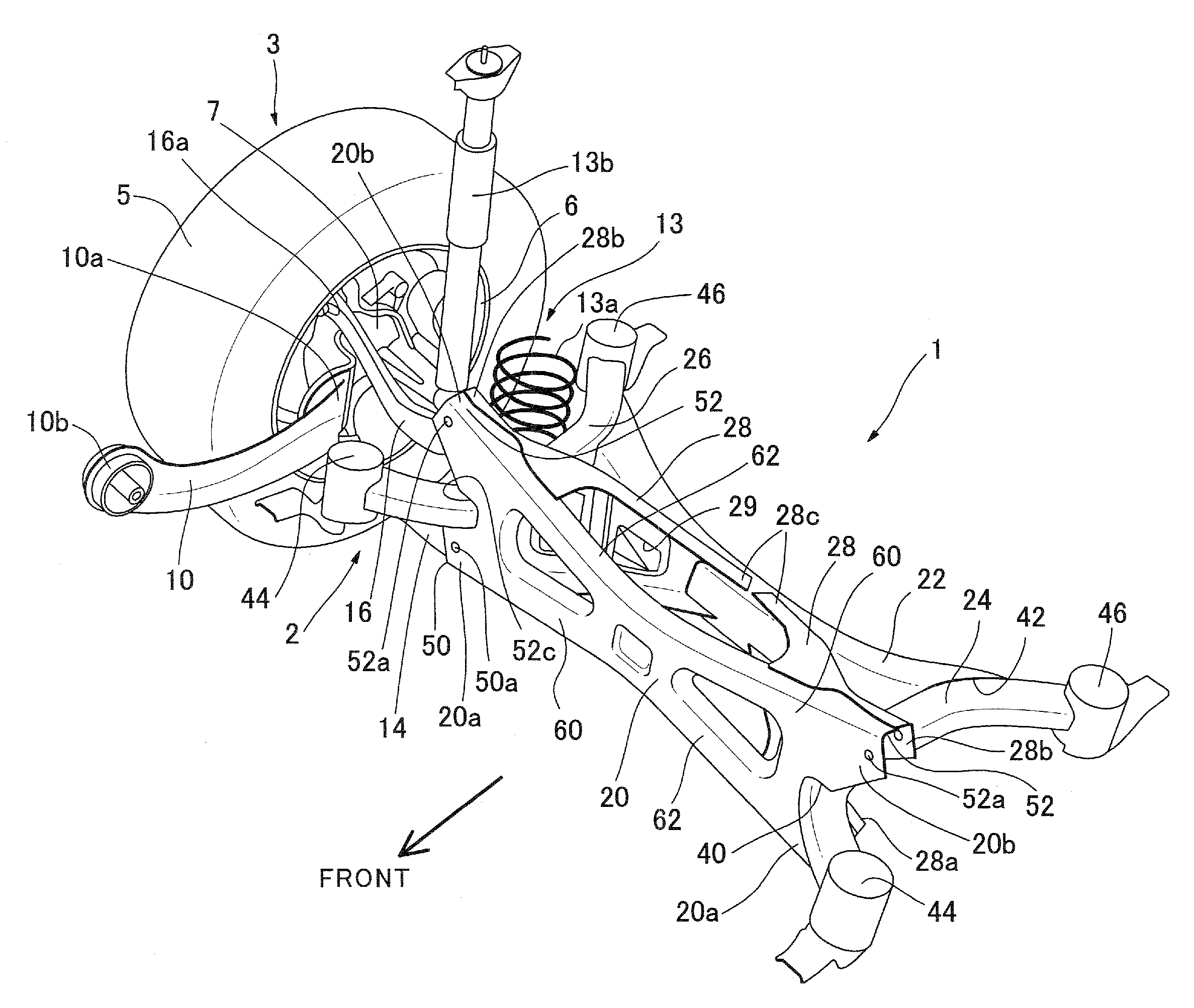
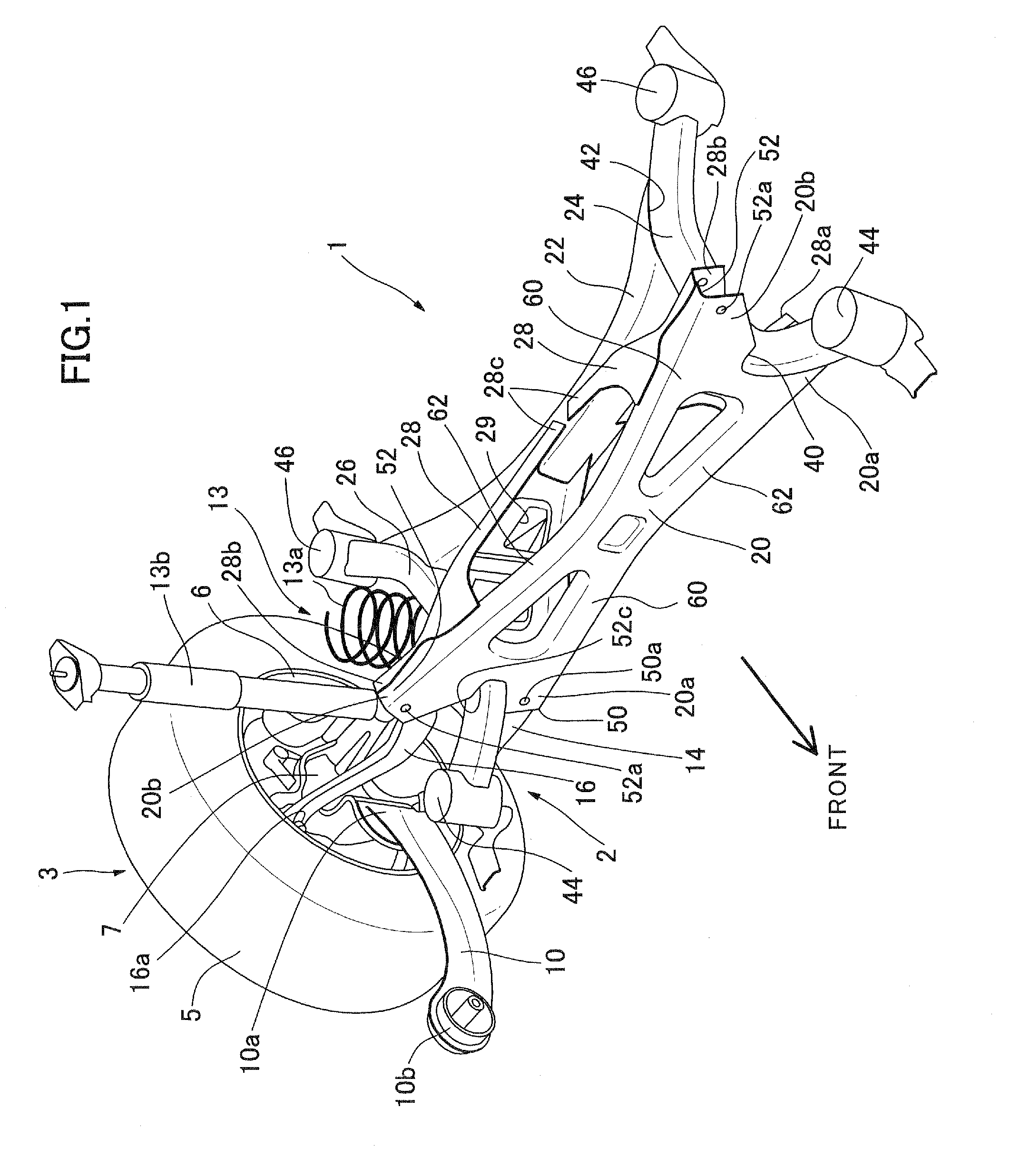
[0071]As shown in FIG. 1, the rear underbody structure employing the suspension subframe structure comprises a rear suspension subframe 1, a pair of right and left rear suspension systems 2 (only a right rear suspension system is illustrated in FIG. 1), and a pair of right and left rear road-wheel assemblies 3 (only a right rear road-wheel assembly is illustrated in FIG. 1). In the following description, as for a pair of components arranged bilaterally symmetrically (e.g., the right and left rear suspension systems 2 and the right and left rear road-wheel assemblies 3), only one of the components will be mainly described, and detailed description about the other component will be omitted on a case-by-case basis. Further, respective components of the right and left rear suspension systems 2 will be distinguished from each other by appending “right” and “left”, respectively, to each component name, according to need.
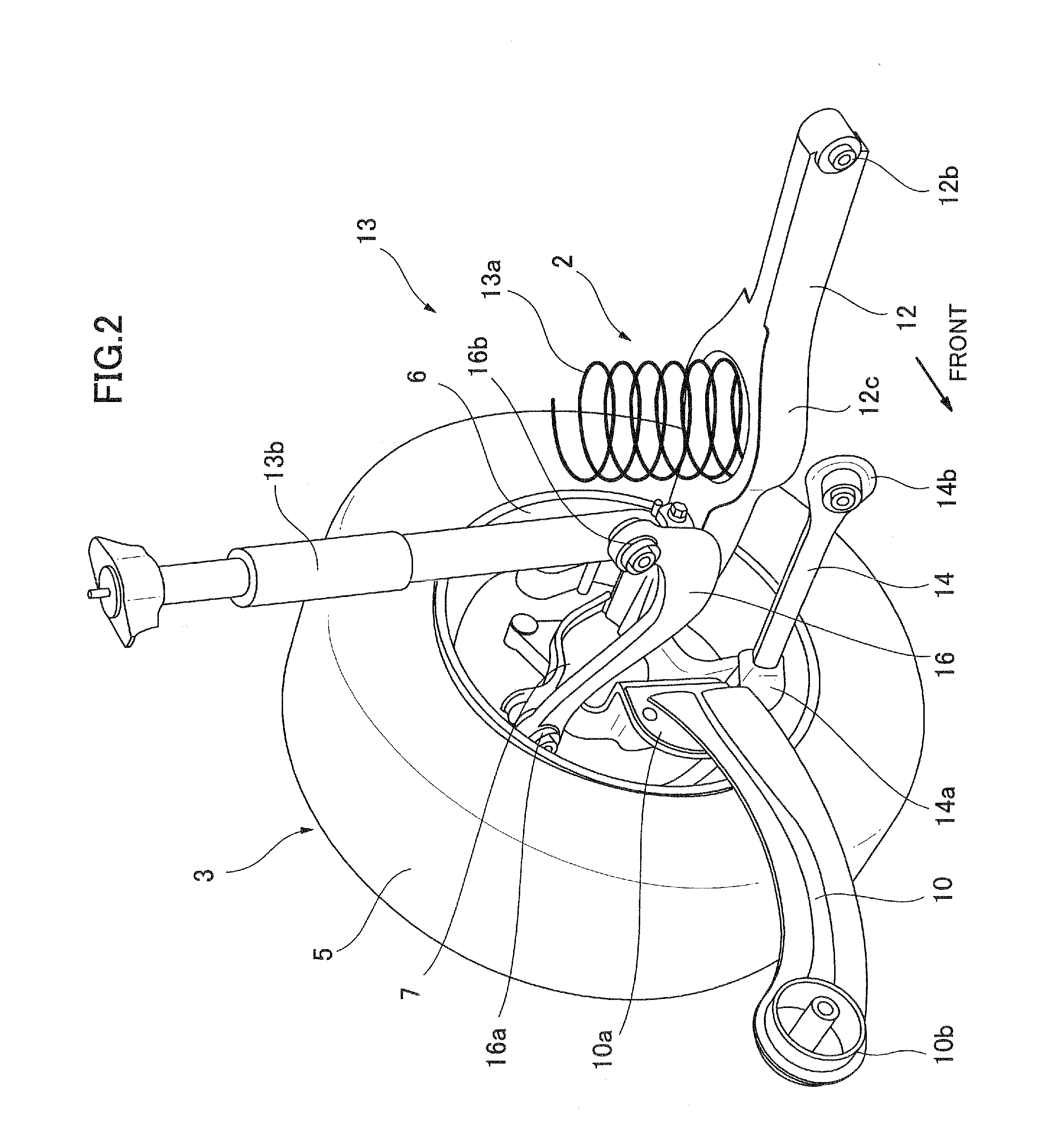
[0072]As shown in FIGS. 1 and 2, the rear road-wheel assembly 3 comp...
second embodiment
[0130]As above, in the suspension subframe structure a structure for increasing the overall rigidity of the rear suspension subframe 101 and a structure for effectively supporting the suspension arms can be designed independently to reliably enhance functions and effects of the respective structures.
[0131]Although the first and second embodiments have been described based on one example where the multi-link suspension system is an E-type multi-link suspension system, it is understood that the present invention may be applied to a subframe structure for any other suitable type of multi-link suspension system. Further, the rear lateral member 22 (122) may be formed in the same configuration as that of the front lateral member 20 (120) in the first or second embodiment. In this case, the reinforcing inclined members 28 may be arranged reversely in the longitudinal direction to receive loads from suspension arms mounted to the rear lateral member 22.
PUM
 Abstract
Description
Claims
Application Information