
Contactless Multispectral Biometric Capture

Active Publication Date: 2009-10-01
HID GLOBAL CORP
View PDF99 Cites 102 Cited by
  • Summary
  • Abstract
  • Description
  • Claims
  • Application Information

AI Technical Summary

Benefits of technology

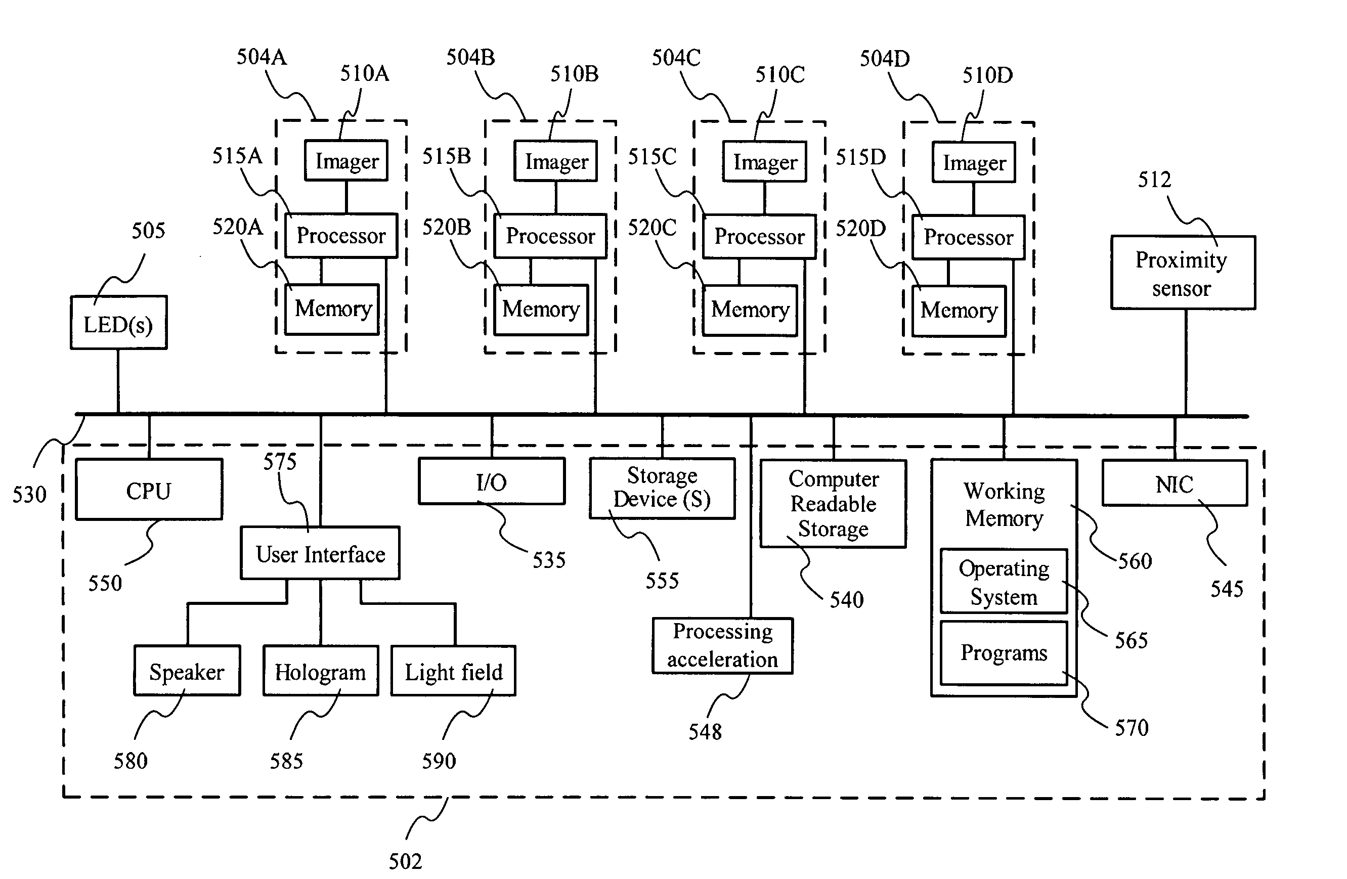
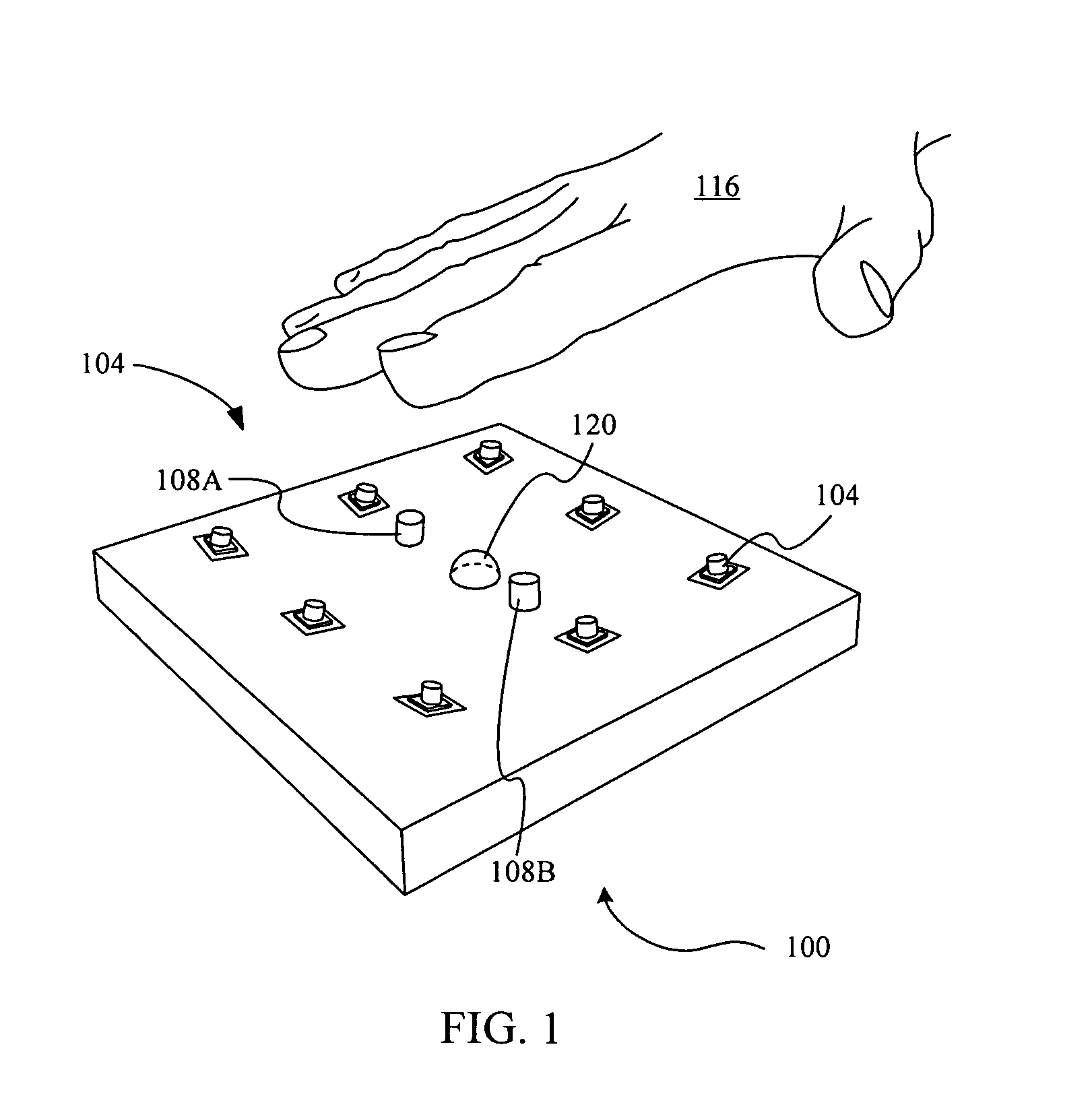
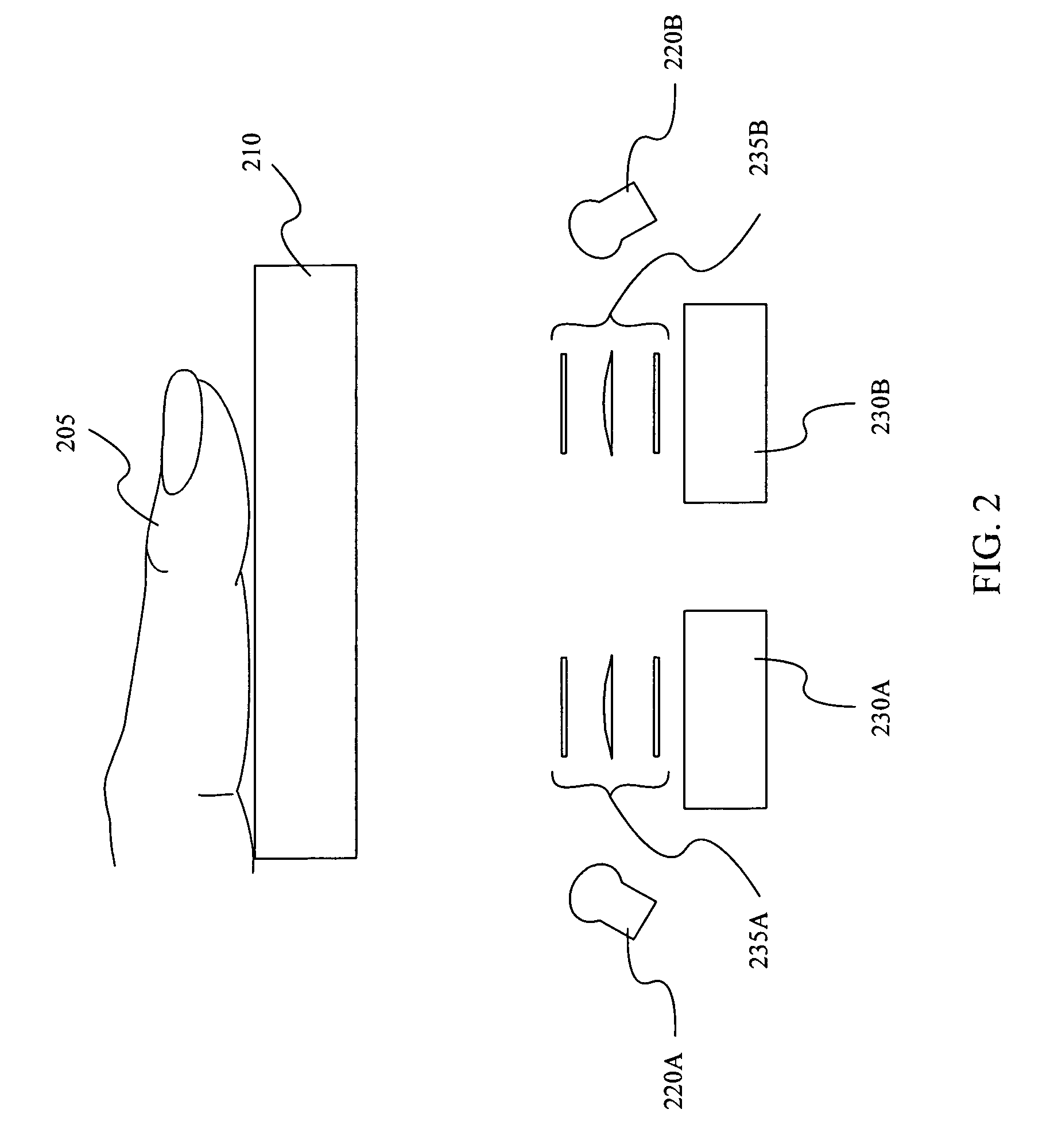
[0009]A biometric system is disclosed according to some embodiments. The biometric system includes one or more illumination sources, a first imager, a second imager and an analyzer. The one or more illumination sources may be configured to illuminate at least a portion of a target space. The target space may be located within free space, in some embodiments, and/or defined partially be a platen or other mechanical device, in other embodiments. In other embodiments, the target space is configured to receive a human hand. The first imager may be configured to receive light from at least a portion of the target space under a first optical condition. The second imager may be configured to receive light

Problems solved by technology

Obtaining adequate contact is both finicky and time-consuming because of factors related to individual characteristics of users of the sensors, the quality of the skin, and environmental variability.
For some individuals and under some circumstances, achieving adequate contact is impossible.
Ease of consistent fingerprint capture limits the effectiveness and scope of applications that utilize fingerprint biometrics for identity management.
Furthermore, in some cultures and during specific public health events, there is a negative perception of contact-based fingerprinting.
Thus, although the fingerprint region is not in contact with the sensor, other portions of the finger are contacting the sensor, which compromises the advantages that a true noncontact fingerprint sensor would embody.
Most existing fingerprint sensors are also susceptible to being defeated through the use of artificial or altered fingerprint samples.
Although each fingerprint technology may be susceptible to only specific types of artificial (or “spoof”) samples, the effort required to spoof most systems is fairly modest one the “trick” for doing so is known.

Method used


Image

  • Contactless Multispectral Biometric Capture
  • Contactless Multispectral Biometric Capture
  • Contactless Multispectral Biometric Capture

Examples


Embodiment Construction

[0066]A detailed description is provided below of examples of multispectral systems that may accordingly be used in embodiments, but such a description is not intended to be limiting since other techniques may be used in alternative embodiments.

[0067]Overview

[0068]Embodiments disclosed herein provide methods and systems that allow for the collection and processing of biometric measurements. These biometric measurements may provide strong assurance of a person's identity, as well as of the authenticity of the biometric sample being taken. Such embodiments, for example, may be incorporated within a number of different types of devices, such as cellular telephones, personal digital assistants, laptop computers, and other portable electronic devices, as well as stand-alone devices for physical or logical access. The common characteristic of the methods and systems is the application of multiple distinct optical configurations used to collect a plurality of image data during a single ill...


PUM


Abstract

A number of biometric systems and methods are disclosed. A system according to one embodiment includes an illumination subsystem, an imaging subsystem, and an analyzer. The illumination subsystem is disposed to illuminate a target space. The imaging subsystem is configured to image the target space under distinct optical conditions. The analyzer is provided in communication with the illumination subsystem, the imaging subsystem, and the three-dimensional subsystem. The analyzer also has instructions to operate the subsystems to collect substantially simultaneously a plurality of images of the object disposed at the predetermined spatial location under multispectral conditions.

Description

CROSS-REFERENCES TO RELATED APPLICATIONS[0001]This application is a non-provisional, and claims the benefit, of commonly assigned U.S. Provisional Application No. 60 / 943,207, filed Jun. 11, 2007, entitled “Contactless Multispectral Biometric Capture,” the entirety of which is herein incorporated by reference for all purposes.[0002]This application is a continuation-in-part of U.S. patent application Ser. No. 12 / 100,597, filed Apr. 10, 2008, entitled “Biometric Detection Using Spatial, Temporal, And / Or Spectral Techniques,” which is a nonprovisional, and claims the benefit, of U.S. Provisional Patent Application No. 60 / 911,007, filed Apr. 10, 2007, entitled “Spatial And Temporal Biometric Detection,” the entire disclosure of each of which is incorporated herein by reference for all purposes.[0003]This application is a continuation-in-part of U.S. patent application Ser. No. 11 / 779,998, filed Jul. 19, 2007, entitled “Multibiometric Multispectral Imager,” which is a nonprovisional, and...

Claims


Application Information

Patent Timeline
IPC IPC(8): G06K9/00G06V10/143
CPCG06K9/2018G06K9/00033G06V40/1312G06V10/143
Inventor ROWEENNIS, MATTHEWCORCORAN, STEPHEN P.
Owner HID GLOBAL CORP
Learn More