
Toner supply device, developing unit and toner supply device remanufacturing method

Inactive Publication Date: 2009-10-01
SHARP KK
View PDF6 Cites 0 Cited by
  • Summary
  • Abstract
  • Description
  • Claims
  • Application Information

AI Technical Summary

Benefits of technology

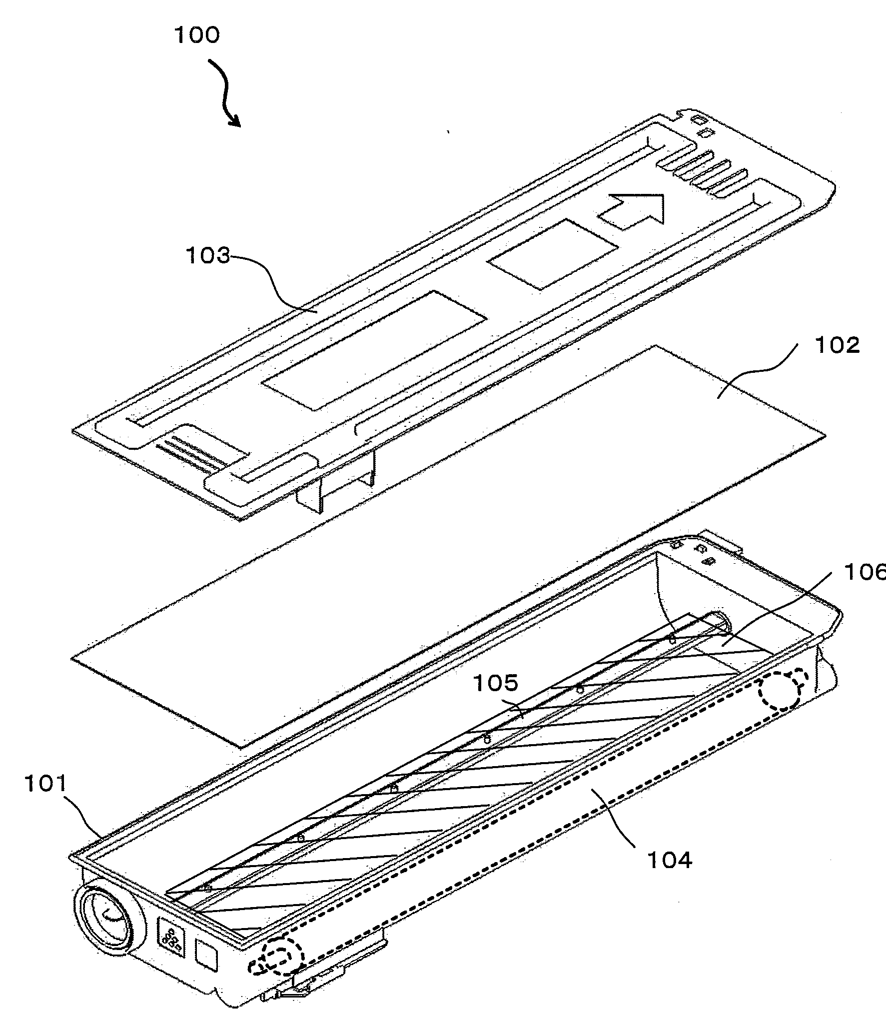
[0012]The present invention has been devised in view of the conventional problems described above, it is therefore an object of the present invention to provide a toner supply device including a toner supply container filled with toner, which is reduced in the remanufacturing time when it is remanufactured and hence is reduced in the total cost.

Problems solved by technology

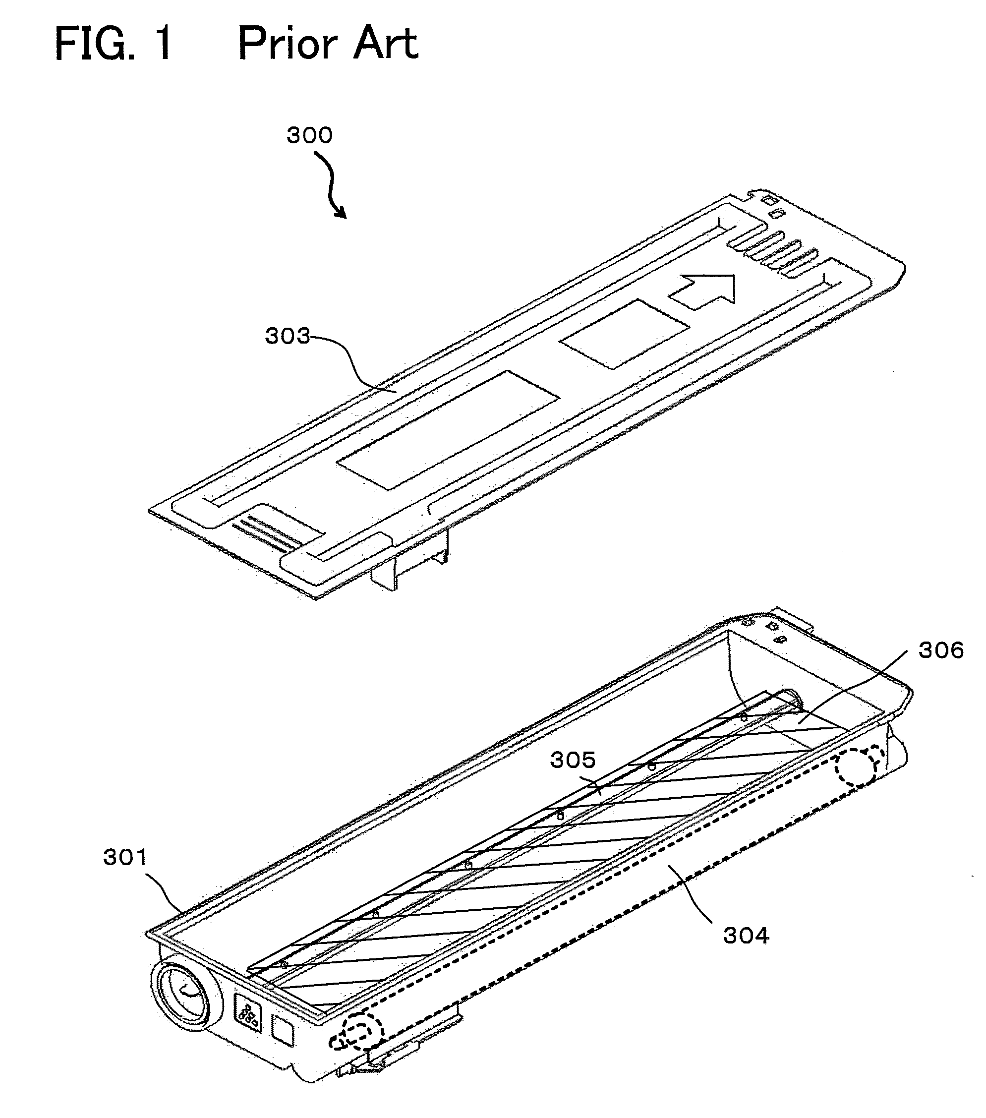
However, in the kinds of the toner supply devices disclosed in patent documents 1 and 2, no remanufacturing process has been taken into account.
Hence, when the device is disjoined or broken down at the joint plane, burrs and cracks arise at the resin surfaces, so that it is impossible to reuse them or it is necessary to prepare a new storage container (storage casing) and the like.
In particular, as to the toner supply containers including various parts such as a toner supply roller etc., it is necessary to collect each part individually and separately, hence it is not a good measure to discard them or bring them to a plastic recycling process.

Method used


Image

  • Toner supply device, developing unit and toner supply device remanufacturing method
  • Toner supply device, developing unit and toner supply device remanufacturing method
  • Toner supply device, developing unit and toner supply device remanufacturing method

Examples


Embodiment Construction

[0034]A preferred embodiment of the present invention will hereinafter be briefly described with reference to the accompanying drawings. Here, in this specification and drawings, repeated description of constituents having substantially the same functional configurations will be omitted by allotting the same reference numerals.

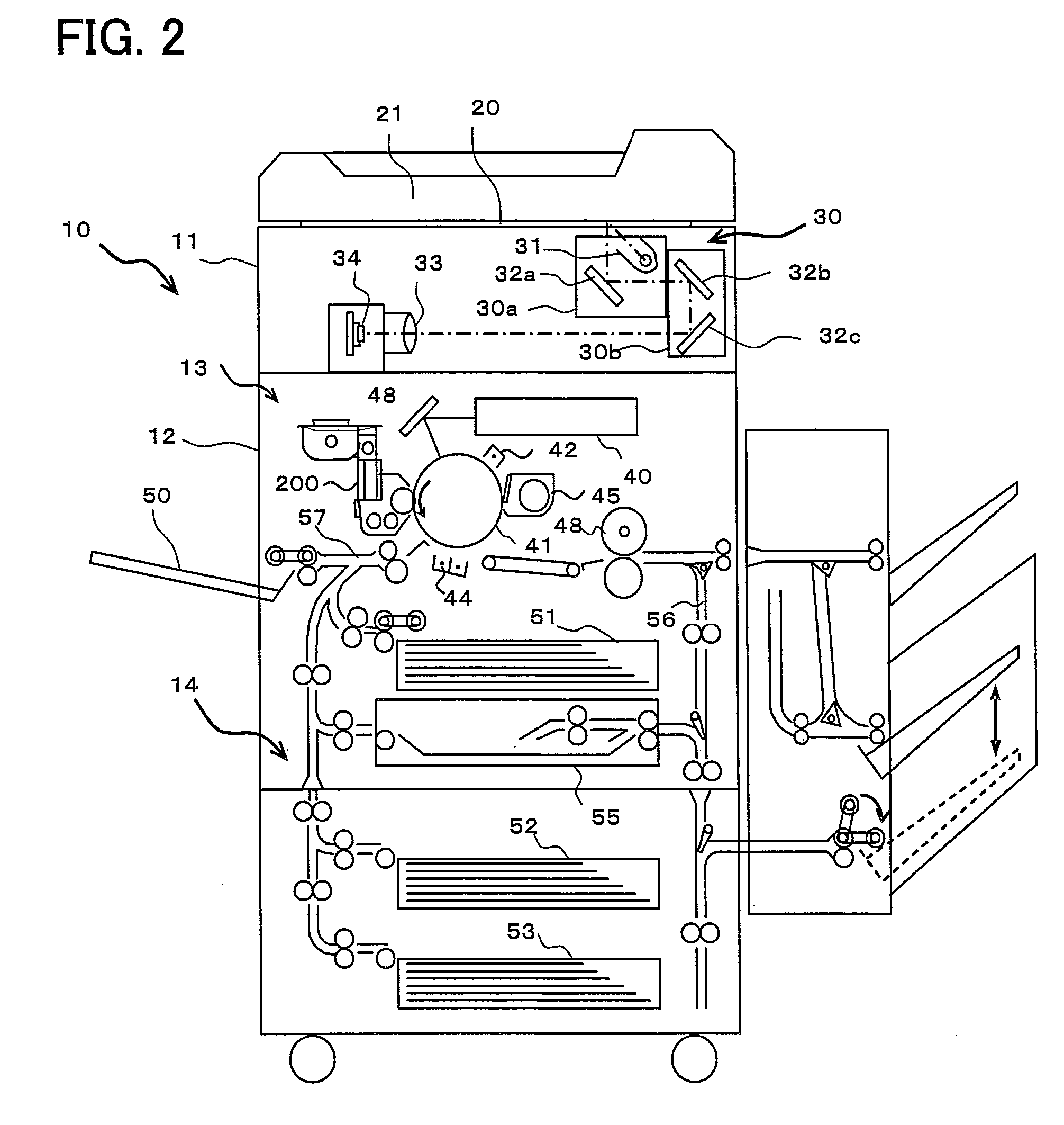
[0035]FIG. 2 is a schematic configurational view showing the overall configuration of an image forming apparatus (digital copier) on which a toner supply device (developer supply device) according to the present invention is mounted.

[0036]As shown in FIG. 2, a digital copier 10 is essentially composed of a scanner portion 11 and a printer portion 12 including an image forming portion 13, a paper feed portion 14, etc.

(Description of Scanner Portion 11)

[0037]Arranged on a document table 20 made of transparent glass on the top surface of scanner portion 11 is an automatic document feeder 21. Automatic document feeder 21 is an device for automatically feeding the ...


PUM


Abstract

A toner supply device includes a toner storage tank for storing toner; a toner supply roller for discharging toner; a covering member for covering the top surface of the toner storage tank filled with toner; and a sealing element provided between the toner storage tank and the covering member.

Description

[0001]This Nonprovisional application claims priority under 35 U.S.C. §119(a) on Patent Application No. 2008-82651 filed in Japan on 27 Mar. 2008, the entire contents of which are hereby incorporated by reference.BACKGROUND OF THE INVENTION[0002](1) Field of the Invention[0003]The present invention relates to a toner supply device including a toner supply roller, for use in an image forming apparatus for forming images with toner and a developing unit using the toner supply device as well as to a toner supply device remanufacturing method.[0004](2) Description of the Prior Art[0005]Conventionally, in image forming apparatuses using toner, such as copiers, facsimile machines, etc., a toner supply device such as a toner container, toner cartridge or the like is used to supply toner to the developing unit so as to deal with continuous operation of image output.[0006]Since toner supply devices such as toner containers, toner cartridges, etc., receive vibrations and impacts during shipme...

Claims


Application Information

Patent Timeline
IPC IPC(8): G03G15/08
CPCG03G15/0894G03G2215/0604G03G2215/069G03G15/0855G03G15/0875G03G15/0865G03G2215/0838
Inventor KIMURA, TAKAHIKOUSUI, TOMOYADEGUCHI, MASANOBUSUDOH, TERUYOSHI
Owner SHARP KK
Learn More