Assumption torque setting device, automatic transmission controller, and method for learning internal combustion engine delay model

a technology of automatic transmission controller and setting device, which is applied in the direction of electric control, machines/engines, instruments, etc., can solve the problems of inaccurate hypothetical engine torque, inaccurate transmission control based on hypothetical engine torque, and producing gear shifting shock, etc., to suppress the gear shifting shock and high accuracy assumption torque. , the effect of high accuracy and smooth gear shift control

Inactive Publication Date: 2009-10-01
TOYOTA JIDOSHA KK
View PDF4 Cites 2 Cited by
  • Summary
  • Abstract
  • Description
  • Claims
  • Application Information

AI Technical Summary

Benefits of technology

[0005]It is an object of the present invention to obtain a highly accurate assumption torque that smoothly varies during a gear shifting period by taking the response state into consideration. Another object of the present invention is to realize highly accurate and smooth gear shift control by suppressing the gear shifting shock. A further object of the present invention is to provide a method for learning or determining an internal combustion engine delay model that contributes to obtaining a highly accurate assumption torque.

Problems solved by technology

In such a case, this would increase the difference between the line pressure actually required when completing the gear shifting period and the held line pressure and thereby produce a gear shifting shock.
Thus, the response state of the actual output torque relative to the target torque in the internal combustion engine is not taken into consideration, and the hypothetical engine torque is not accurate.
Accordingly, the automatic transmission control based on such hypothetical engine torque is not accurate, and therefore a step is formed between the hypothetical engine torque and the actual torque when gear shifting is completed.
This may produce gear shifting shock.

Method used


Image

  • Assumption torque setting device, automatic transmission controller, and method for learning internal combustion engine delay model
  • Assumption torque setting device, automatic transmission controller, and method for learning internal combustion engine delay model
  • Assumption torque setting device, automatic transmission controller, and method for learning internal combustion engine delay model

Examples


first embodiment

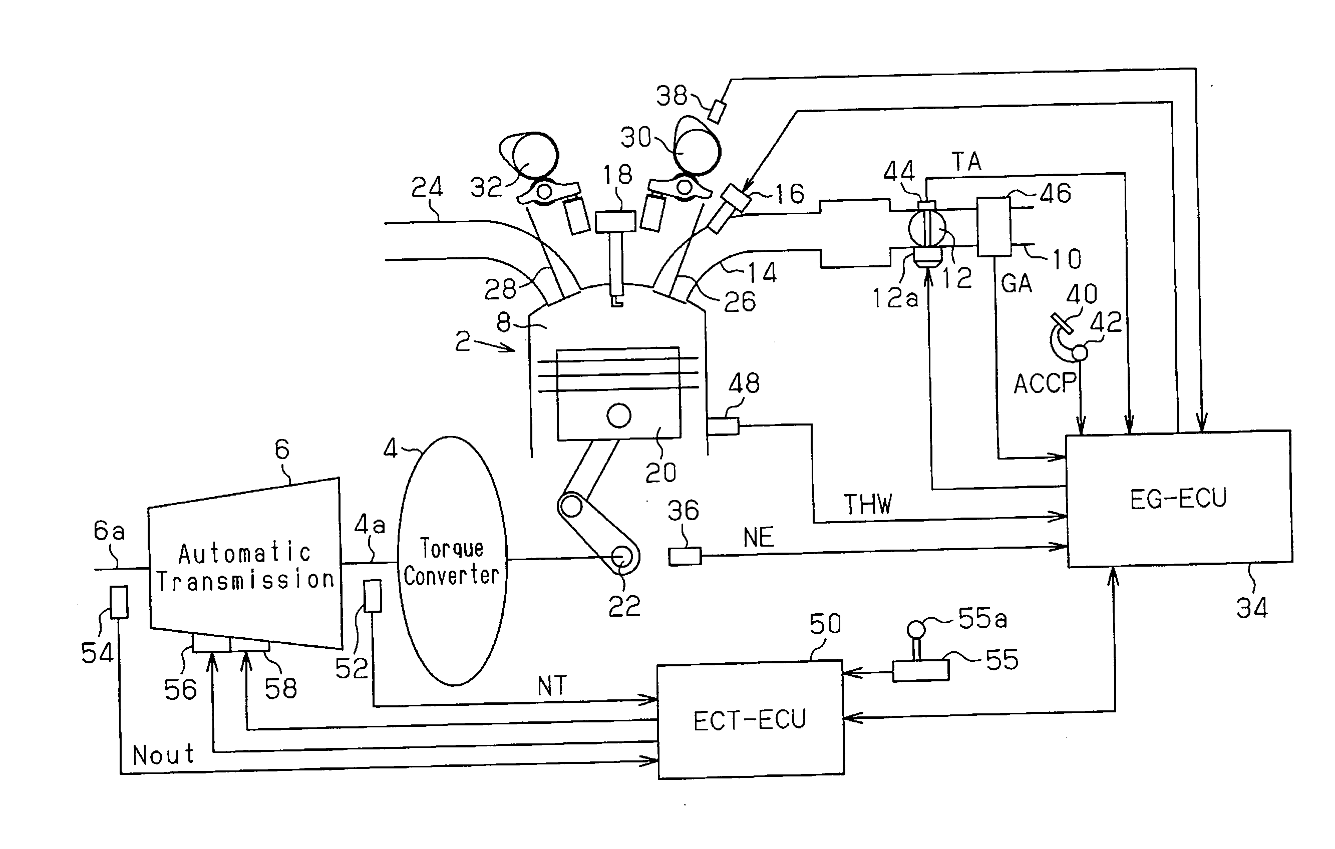
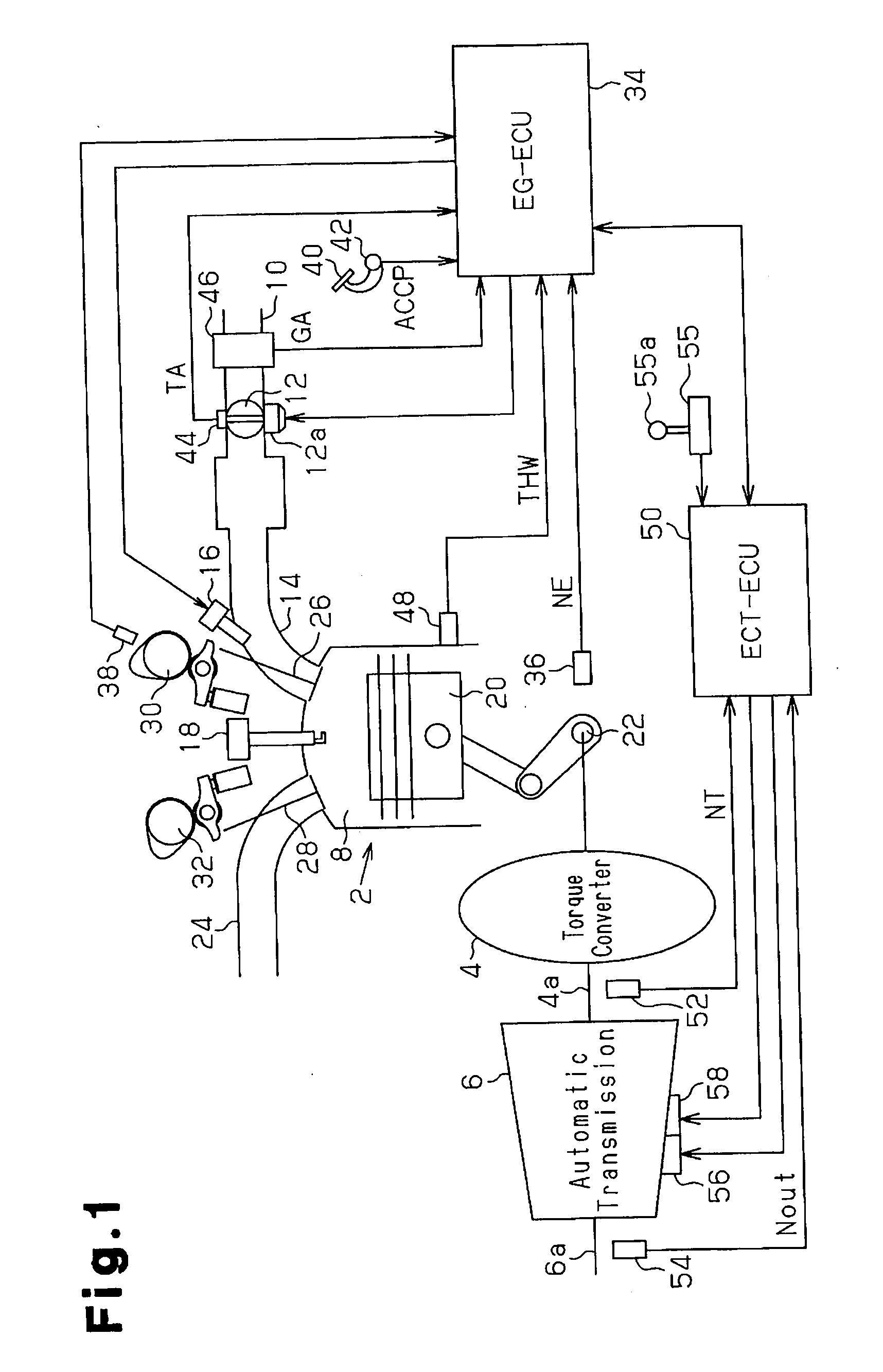
[0029]FIG. 1 is a schematic block diagram showing the structure of a vehicle internal combustion engine, a drive system, and a control system to which the present invention is applied. The internal combustion engine is a gasoline engine (hereinafter simply referred to as the engine) 2. The drive system includes a torque converter 4 and an automatic transmission 6. The rotational drive force of the engine 2, which is transmitted to the automatic transmission 6 via the torque converter 4 to shift gears, is output to the wheels as vehicle travelling drive force.

[0030]The engine 2 is an in-line 4-cylinder engine, V-6 cylinder engine, or the like. A combustion chamber 8 is defined in each cylinder of the engine 2. The combustion chamber 8 is supplied with ambient air and fuel through an intake port 14. The air is drawn into an intake passage 10 and regulated by a throttle valve 12. An air filter is located at the distal end of the intake passage 10. The fuel is injected from a fuel injec...

second embodiment

[0061]In this embodiment, the line pressure control process shown in FIG. 5 is executed in lieu of that shown in FIG. 2 during gear shifting. Furthermore, a torque reduction process reflecting torque difference calculation process shown in FIG. 6 is executed. The delay model change addition torque calculation process (FIG. 3) is executed in the same manner as the first embodiment. Otherwise, the second embodiment is the same as the first embodiment. Therefore, the second embodiment will be discussed with reference to FIG. 1.

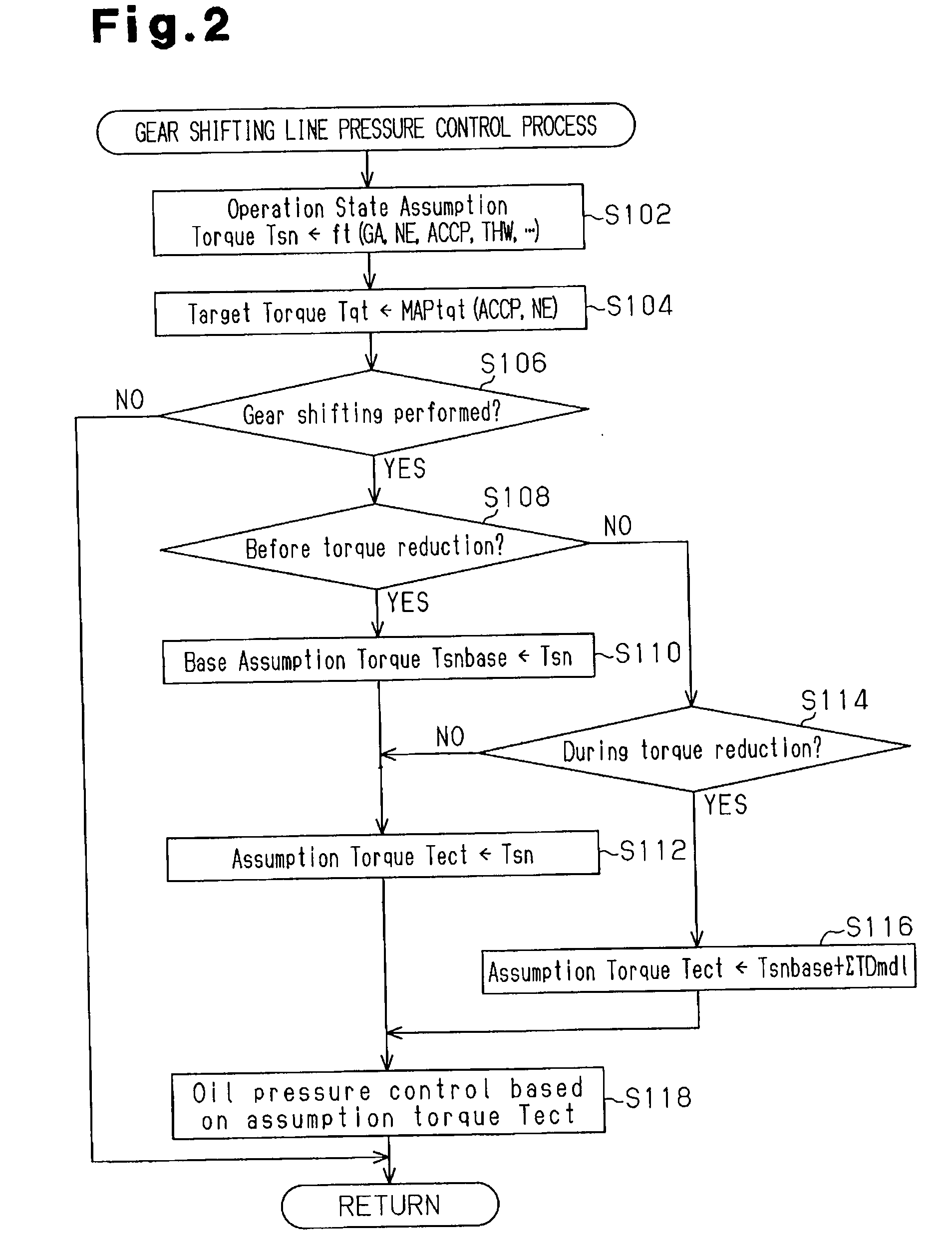
[0062]The line pressure control process (FIG. 5) differs from that of FIG. 2 in that the calculation of the assumption torque Tect (step S216) is performed using equation 4 instead of equation 1 of the first embodiment during torque reduction (“YES” in step S214). Steps S202 to S214 and S218 are the same as steps S102 to S114 and S118 of FIG. 2.

Tect←Tsnbase+ΣTDmdl+dTms   [Equation 4]

[0063]The assumption model torque change amount ΣTDmdl, which is as described in ...

third embodiment

[0077]In this embodiment, a delay model change addition torque calculation process shown in FIG. 8 is executed in lieu of that in the first or the second embodiment and shown in FIG. 3. Otherwise, the third embodiment is the same as the first or the second embodiment. Therefore, the third embodiment will be discussed with reference to FIGS. 1, 2, 5, and 6.

[0078]The delay model change addition torque calculation process (FIG. 8) of this embodiment is executed in the same cycle as FIG. 3. However, the calculation of the assumption model torque cycle change amount TDmdl is different.

[0079]When the delay model change addition torque calculation process (FIG. 8) starts, the assumption model torque Tmdl is first calculated based on the target torque Tqt by the internal combustion engine delay model (step S342). This process is the same as step S142 of FIG. 3 and is calculated by using equation 2.

[0080]The assumption model torque Tmdl is then calculated and stored as time-series data Wtmdl...


PUM


Abstract

An assumption torque setting device for an engine that executes a torque reduction process during gear shifting. The device sets a torque assumed to be output by the engine and based on a target torque from which an amount corresponding to the torque reduction process is excluded as an assumption torque during the gear shifting. The device includes an assumption model torque calculation unit which calculates an assumption model torque from the target torque from which an amount corresponding to the torque reduction process is excluded based on an internal combustion engine delay model. An assumption torque calculation unit calculates before torque reduction is performed an assumption torque based on an engine operation state and calculates when the torque reduction is being performed an assumption torque based on the assumption model torque and an assumption torque calculated from the engine operation state.

Description

BACKGROUND OF THE INVENTION[0001]The present invention relates to an assumption torque setting device for setting, in an internal combustion engine that executes a torque reduction process during a gear shifting period, a torque assumed to be output by the internal combustion engine that is based on a target torque from which an amount corresponding to the torque reduction process is excluded as an assumption torque during the gear shifting period. The present invention also relates to an automatic transmission controller using the assumption torque setting device. Further, the present invention relates to a method for learning or determination of an internal combustion engine delay model that can be applied to the assumption torque setting device and the automatic transmission controller.[0002]Japanese Laid-Open Patent Publication No. 5-280625 (pp. 4-5, FIG. 7) proposes a technique for holding a line pressure in an automatic transmission calculated from an input torque when a gear ...

Claims


Application Information

Patent Timeline
Patent Type & Authority Applications(United States)
IPC IPC(8): G06F19/00F16H59/74F16H59/14F16H61/04F16H61/68F16H61/684F16H63/50
CPCF02D41/023F02D41/107F02D41/1497F02D41/2441F02D41/2451Y10T477/677F02D2200/1004F02D2250/21F16H59/14F16H63/502F16H2306/42F02D2041/1433
Inventor KUWAHARA, SEIJIKAIGAWA, MASATO
Owner TOYOTA JIDOSHA KK
Why Eureka
Try Eureka