Compact Tripod

a tripod and compact technology, applied in the field of tripods, can solve the problems of limited number of threaded portions on each leg, and achieve the effect of reducing dimensions

Inactive Publication Date: 2009-10-08
LINO MANFROTTO & CO SPA
View PDF17 Cites 39 Cited by
  • Summary
  • Abstract
  • Description
  • Claims
  • Application Information

AI Technical Summary

Benefits of technology

[0007]The technical problem considered by this invention is that of providing a tripod which is structurally and functionally designed to overcome all the disadvantages mentioned with reference to the known art while at the same time minimising dimensions in the closed position.

Problems solved by technology

The number of threaded portions on each leg is however limited, both by technical and dimensional reasons and by reasons of an economic nature.
The further benefit which can be achieved in this way is however relatively small.

Method used


Image

  • Compact Tripod
  • Compact Tripod
  • Compact Tripod

Examples


Embodiment Construction

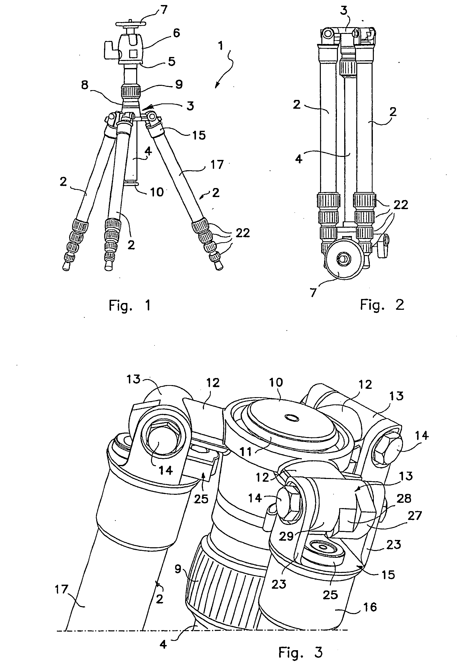
[0015]In the figures, 1 indicates as a whole a tripod mainly but not exclusively intended for the support of optical and / or photographic equipment constructed according to this invention.

[0016]Tripod 1 comprises three identical legs, all indicated by 2, converging on a spider 3 to the center of which a column 4 is movably attached. Column 4 has a support 5 at one end for a head 6 which is in turn provided with a plate 7 on which the equipment in use can be removably fixed. Plate 7 can be orientated within a substantially hemispherical space through a spherical joint which is not shown. One of the possible orientation positions is that shown in FIG. 2, with the tripod closed, to which reference will be made below.

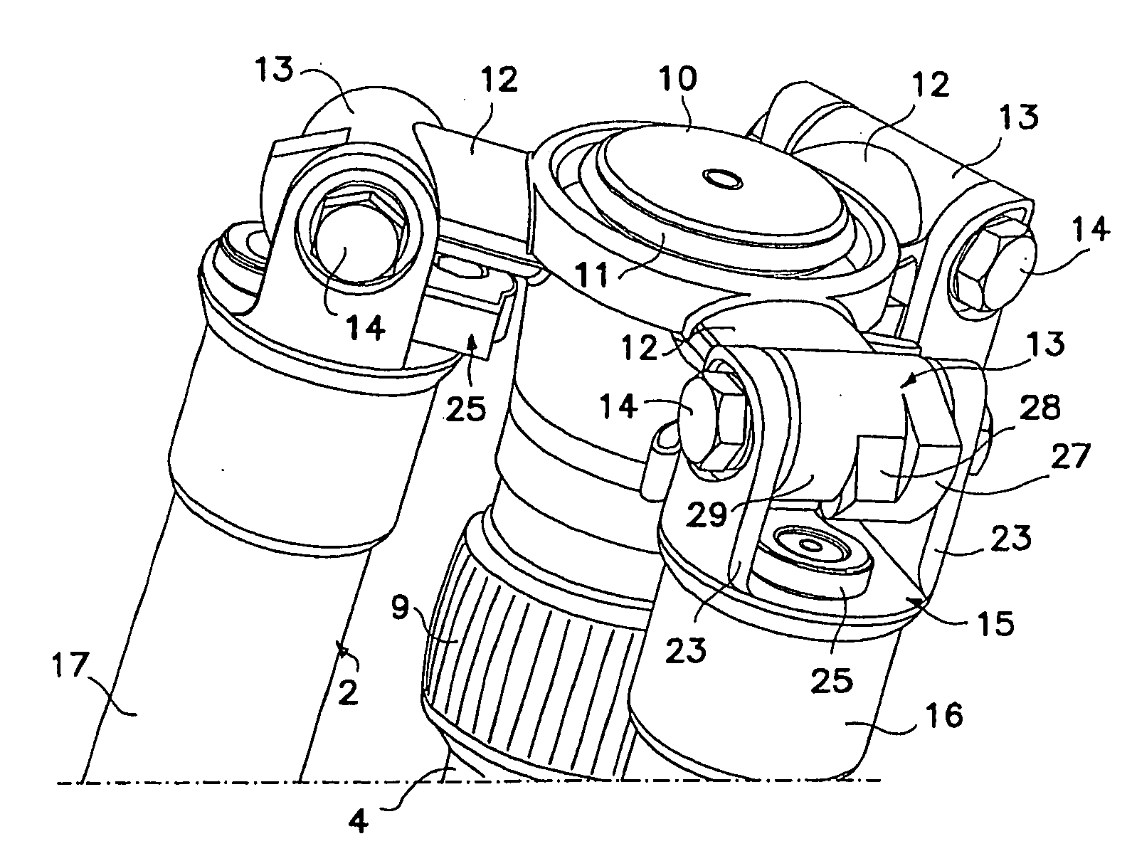
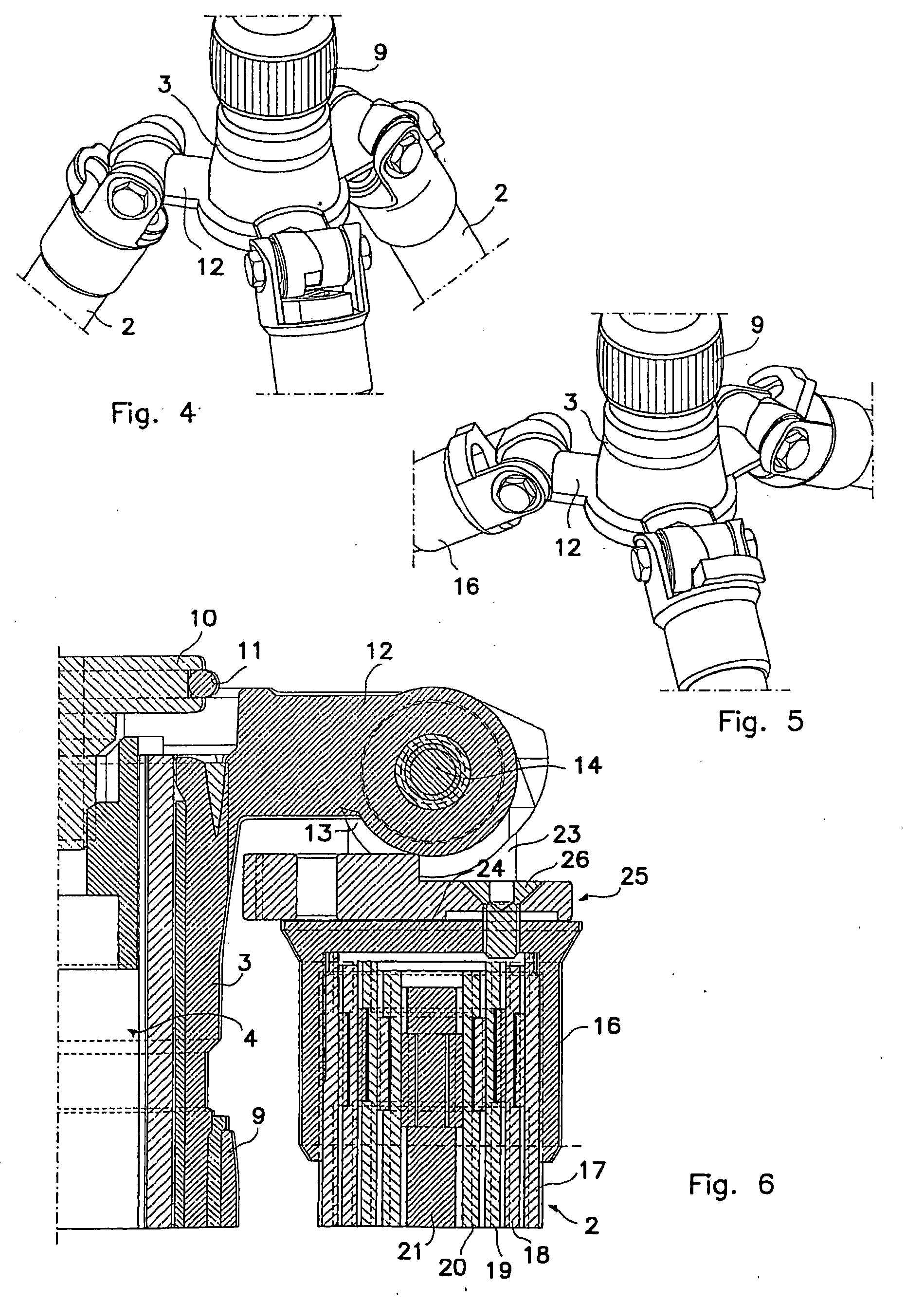
[0017]Column 4 is movably guided within a central hub 8 of spider 3 and can be immobilized in an adjustable position through tightening a collar 9. On the side opposite head 6 the latter is provided with a disc-shaped stop 10 surrounded around its perimeter by a resilient el...


PUM


Abstract

A compact tripod includes at least three legs converging on a spider and hinged thereto at one end by a corresponding hinge sleeve and fork member. A support is provided for a head mounted on the spider in a position such that it projects from the spider opposite the legs when the tripod is open in an operating position. The hinge sleeve and fork member are designed to allow the legs to be folded back from the part of the support when the tripod is closed in a non-operating position. Additionally, the hinge sleeve and fork member include a toothed element and a corresponding stop for the toothed element which are capable of interacting together to limit the extent by which the legs open with respect to the spider.

Description

[0001]This application is a U.S. National Phase Application of PCT International Application PCT / EP2005 / 000022.TECHNICAL FIELD[0002]This invention relates to a tripod, designed particularly but not exclusively for the support of optical and / or photographic equipment. In this context the term “tripod” is to be understood to indicate a support including at least three legs which converge in a spider to which the legs are hinged at one end.TECHNOLOGICAL BACKGROUND[0003]Within this specific technical field a need has been felt to provide tripods which are particularly compact when closed into a carrying position.[0004]On the other hand it is likewise required that tripods should extend to a maximum when open in the operating position. The two requirements are obviously conflicting.[0005]In order to reconcile these two conditions, there have been tripods with telescopic legs with multiple sections or threaded portions which have minimum dimensions when in the closed position. The number ...

Claims


Application Information

Patent Timeline
Patent Type & Authority Applications(United States)
IPC IPC(8): F16M11/38F16M11/16F16M11/32
CPCF16M11/32F16M11/16
Inventor RAYNAUD, GUY
Owner LINO MANFROTTO & CO SPA
Why Eureka
Try Eureka