Spiral drive fastener with friction engageable surface

a friction engageable surface and fastener technology, applied in the direction of fastening means, screws, fastener tools, etc., can solve the problems of high localized stress, difficult design considerations, and limited contact between the driver and the recess surface, and achieve the effect of reducing the distance at the bottom of the recess between the opposing transition surfaces and minimizing any change in dimension

Inactive Publication Date: 2007-11-13
PHILLIPS SCREW
View PDF26 Cites 29 Cited by
  • Summary
  • Abstract
  • Description
  • Claims
  • Application Information

AI Technical Summary

Benefits of technology

[0016]To generate an interference fit, the transition surface is constructed with a slight draft of up to 2° in which the distance at the bottom of the recess between opposing transition surfaces is slightly reduced. The standard driver will be insertable in a normal manner up to a predetermined depth after which the reduced dimension will cause an interference with the mating transition surfaces on the driver. This is accomplished, while minimizing any change in dimension across the upper opening of the recess. In this manner a “stick fit” feature is provided without appreciably altering the desired full surface area engagement at the installation surfaces.

Problems solved by technology

Such conditions present difficult design considerations, particularly with respect to the drive systems and, more particularly, with threaded fasteners having a driver engageable recess in the fastener head.
In all of these systems, the practical result of the necessity for such clearance is that substantial face-to-face, broad area contact between the driver and recess surfaces is seldom achieved, if at all.
Consequently, when torque is applied by the driver, the forces applied to the screw head tend to be concentrated in localized areas with resulting high localized stresses.
Such localized high stress can plastically deform the recess, forming ramps or other deformations resulting in premature, unintended disengagement of the driver from the recess.
In fact the suggested draft of up to 6 degrees, is far in excess of what would be needed and would significantly interfere with the purpose of the spiral installation surface, which is namely to provide engagement of the driver and fastener along an extended surface area as opposed to the tangential engagement of other drive systems.

Method used


Image

  • Spiral drive fastener with friction engageable surface
  • Spiral drive fastener with friction engageable surface
  • Spiral drive fastener with friction engageable surface

Examples


Embodiment Construction

)

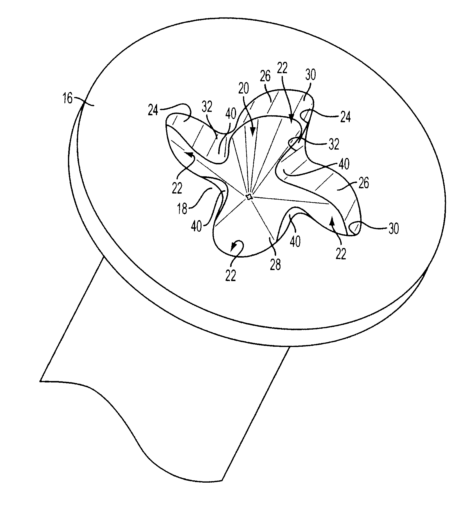
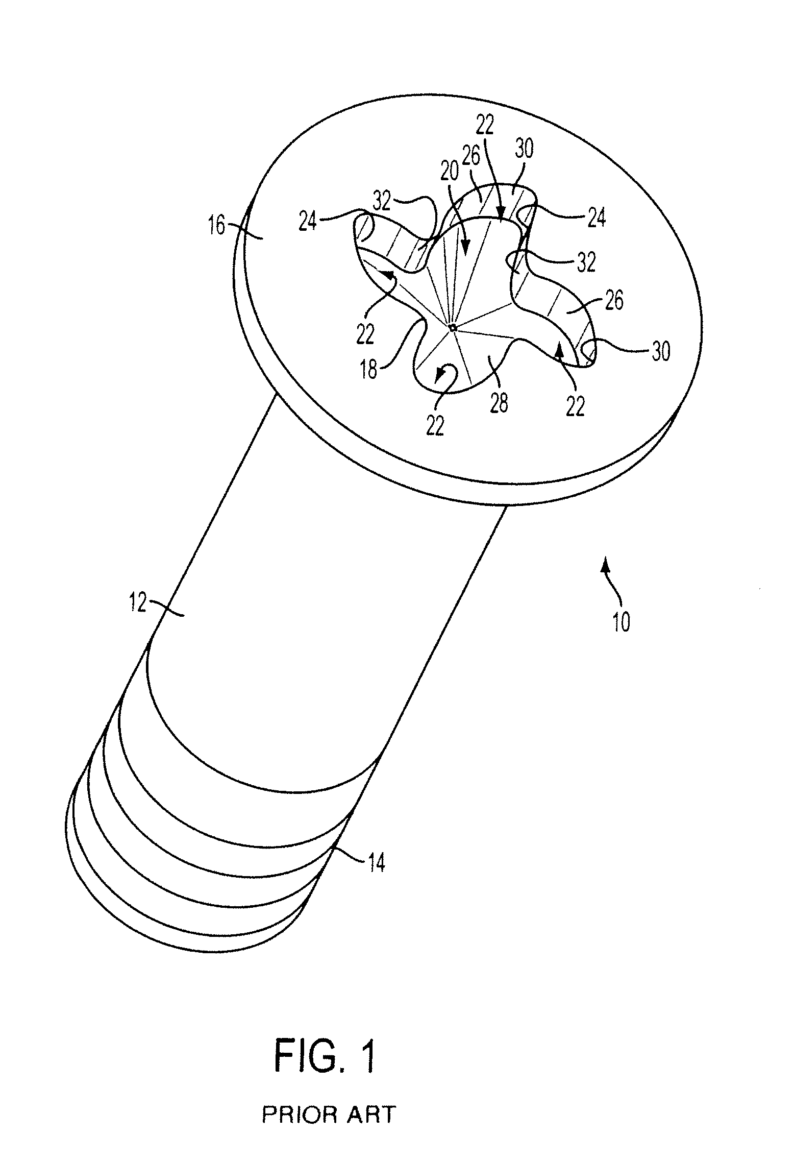
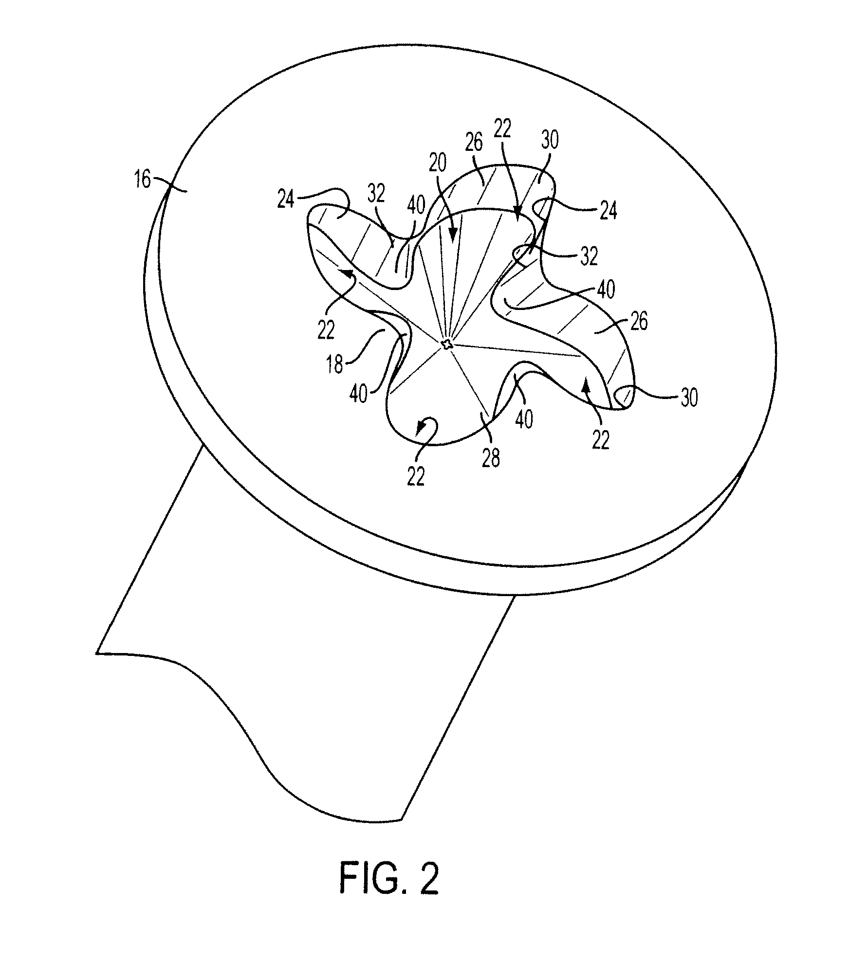
[0028]FIG. 1 illustrates an exemplary threaded fastener 10 having a shank 12 with threads 14 formed at one end and a head 16 with a recess 18 formed at the other end. The head 16 may be formed in a conventional two-blow header machine in which the end of the wire or other material from which the fastener is made is supported in a die of the header machine and its head end is impacted, first with a punch that partially forms the head, and then with a finishing punch that finishes the head and forms the driver-engageable recess. The recess 18 is illustrated as having a central portion 20 and a plurality of radially outwardly extending lobes (wings) 22. The recess in the embodiment of FIG. 1 is formed so that each of its wings 22 has an installation wall 24 (assuming a right-handed thread 14) and a removal wall 26. The installation wall 24 and removal wall 26 preferably are formed to be substantially vertical, defining or closely approximating a cylindrical surface parallel to the lon...


PUM

PropertyMeasurementUnit
angleaaaaaaaaaa
diameteraaaaaaaaaa
radial distanceaaaaaaaaaa

Abstract

Interference surfaces are constructed on inner transition surfaces between wings of a fastener having a spiral recess. A portion of the transition surface is tapered to provide the interference. A standard driver for a spiral recess will engage the interference surface to create a “stick fit” engagement. The punch is formed using a wire EDM operation to construct tapered surfaces within the die cavity of a hob. The hob is machined down to obtain the desired depth, which is measured up from a gage spot indicative of the sticking point.

Description

BACKGROUND OF THE INVENTION[0001]1. Field of the Invention[0002]This application relates in general to drive systems for threaded fasteners, tools for their manufacture, and drivers for applying torque to such fasteners. More specifically this application relates to fasteners that employ winged type drivers. In particular fasteners having a recess that provides spiral driving surfaces.[0003]2. Brief Description of Related Developments[0004]Threaded fasteners commonly used in industrial applications typically are driven by power tools at high speeds and under high torque loads. Such conditions present difficult design considerations, particularly with respect to the drive systems and, more particularly, with threaded fasteners having a driver engageable recess in the fastener head. Ideally, such a drive system should be easily manufactured, both as to recess and head geometry as well as to associated tooling for forming the fastener head and drivers for engaging the recess. The stren...

Claims


Application Information

Patent Timeline
Patent Type & Authority Patents(United States)
IPC IPC(8): F16B23/00B21K5/20B23P15/00
CPCB21K5/20F16B23/0023B23P15/00Y10S411/919F16B23/00
Inventor DILLING, GARY
Owner PHILLIPS SCREW
Why Eureka
Try Eureka