Structure lamp pipe insert connector

a technology for inserting connectors and lamps, which is applied in the direction of screw threaded joints, couplings, rod connections, etc., can solve the problems of unattractive pipe members being drawn, and achieve the effect of reducing shipping dimensions and simple assembly

Inactive Publication Date: 2005-11-10
HSIEH PI HUA
View PDF4 Cites 33 Cited by
  • Summary
  • Abstract
  • Description
  • Claims
  • Application Information

AI Technical Summary

Benefits of technology

[0005] The invention herein provides an improved structure lamp pipe insert connector comprised of a locking connector component situated between upper and lower lamp pipes, the said locking connector component comprised of a threaded rod, a lock sleeve fastened onto the threaded rod, and constraining rings respectively sleeved (not fastened) onto the two ends of the threaded rod and, furthermore, situated at the two sides of the lock sleeve, wherein the interior of the constraining ring is a sloped surface and a plurality of detent slots are disposed along its inner circumferential extent and, after a spring is prepositioned on the sloped surface, it is then sleeved onto the threaded rod. Furthermore, there are revolving guide ring elements with beveled sides, each said revolving guide ring element having guide blocks aligned with the constraining ring detent slot positions and capable of entry into the detent slots, thereby providing for the synchronous rotation of the revolving guide ring elements and the constraining rings; and when the lamp pipes drive the constraining rings into rotation, the revolving guide ring elements force the constraining rings to expand outward and become tightly ensconced within the inner circumference of the lamp pipes; as such, assembly is simple and enables user self-assembly and, furthermore, since each steel tube can be disassembled, shipping dimensions are minimized.

Problems solved by technology

However, such a fixing method requires the forming of stepped edges (due to differing pipe dimensions) on the pipes, resulting in the drawback of unattractive pipe members.

Method used


Image

  • Structure lamp pipe insert connector
  • Structure lamp pipe insert connector
  • Structure lamp pipe insert connector

Examples


Embodiment Construction

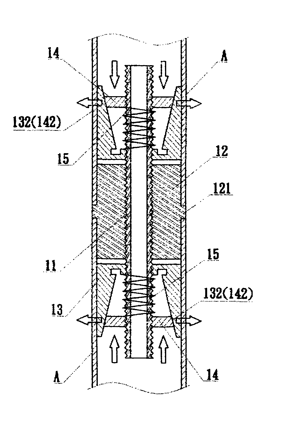
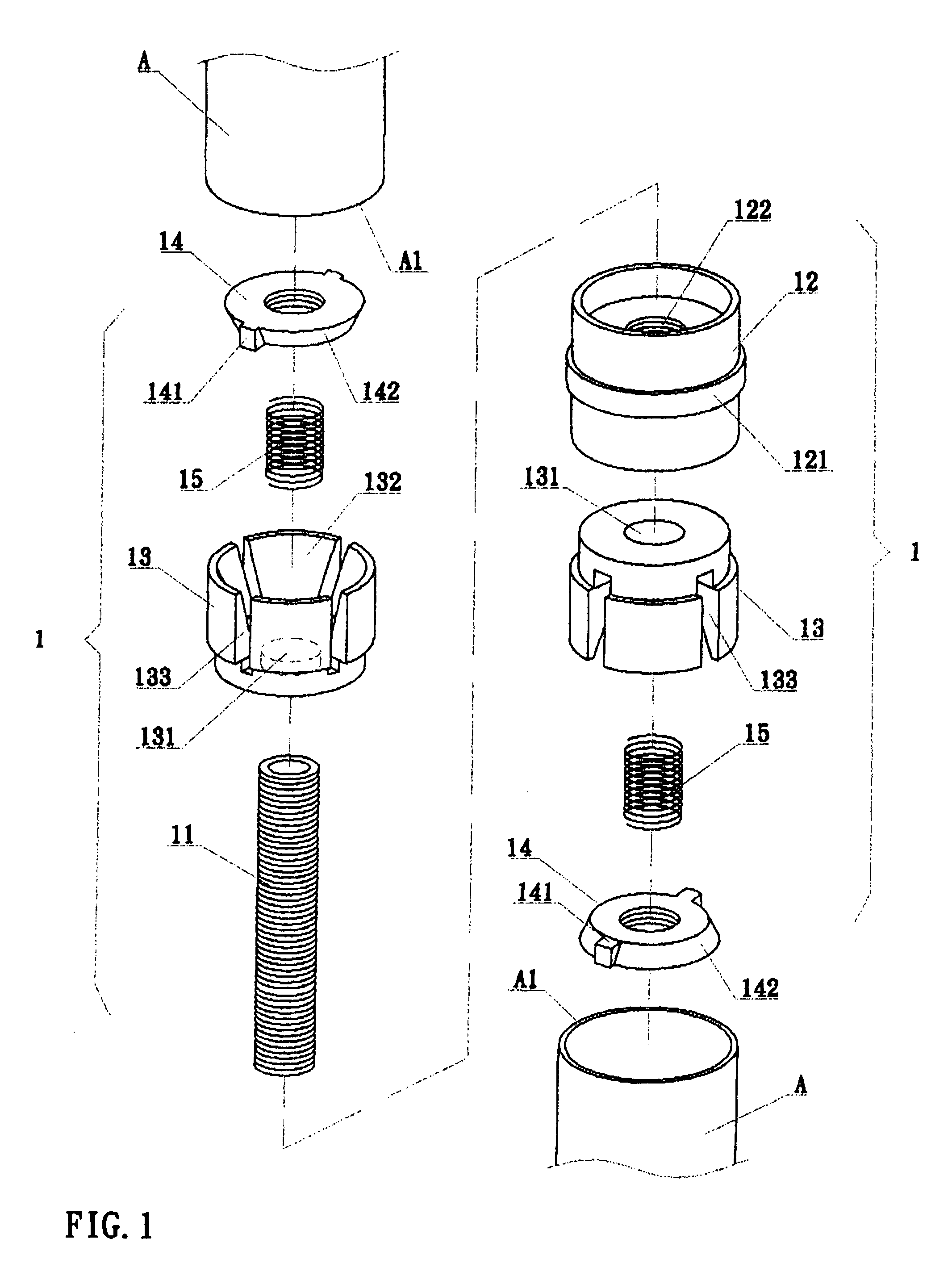
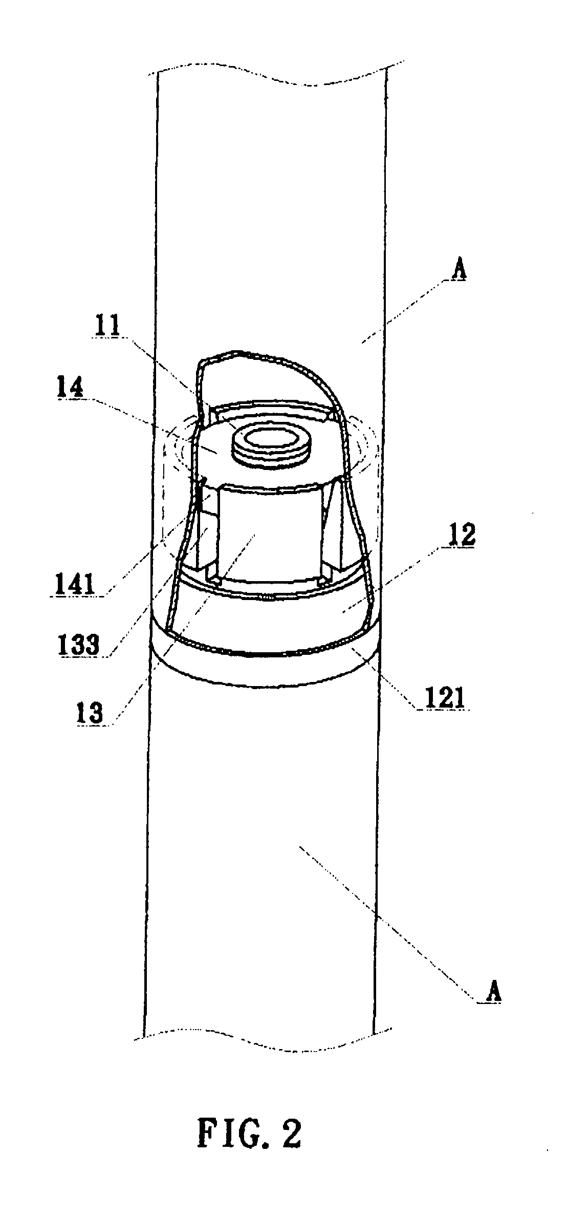
[0012] Referring to FIG. 1 and FIG. 2, the structural arrangement of the invention herein is comprised of a locking connector component 1 situated between upper and lower lamp pipes A, the said locking connector component 1 comprised of a threaded rod 11, a lock sleeve 12 fastened at the center onto the threaded rod 11, and constraining rings 13 respectively sleeved onto the upper and lower ends of the threaded rod 11 and, furthermore, situated at the two sides of the lock sleeve 12.

[0013] The said lock sleeve 12 has an annular band 121 protruding along the center portion of its circumferential surface that provides for the bottoming of the ensleeved extremities A1 of the upper and lower lamp pipes A after their entry; additionally, a threaded hole 122 is formed through the center of the lock sleeve 12 that provides for the fastening of the threaded rod 11.

[0014] Each said constraining ring 13 has a hole 131 (for insertion only, not fastening) through the center that provides for ...


PUM


Abstract

An improved structure lamp pipe insert connector comprised of a locking connector component situated between upper and lower lamp pipes, the locking connector component comprised of a threaded rod, a lock sleeve fastened onto the threaded rod, and constraining rings respectively sleeved (not fastened) onto the two ends of the threaded rod and, furthermore, situated at the two sides of the lock sleeve. The interior of the constraining ring is a sloped surface and a plurality of detent slots are disposed along its inner circumferential extent and, after a spring is prepositioned on the sloped surface, it is then sleeved onto the threaded rod. Furthermore, there are revolving guide ring elements with beveled sides, each revolving guide ring element having guide blocks aligned with the constraining ring detent slot positions and capable of entry into the detent slots, thereby providing for the synchronous rotation of the revolving guide ring elements and the constraining rings. When the lamp pipes drive the constraining rings into rotation, the revolving guide ring element beveled sides are forced against the constraining ring sloped surfaces and become tightly ensconced within the inner circumference of the lamp pipes. As such, assembly is simple and enables user self-assembly and, furthermore, since each steel pipe can be disassembled, shipping dimensions are minimized.

Description

BACKGROUND OF THE INVENTION [0001] 1) Field of the Invention [0002] The invention herein relates to an improved structure lamp pipe insert connector comprised of a locking connector component in which the interior of each constraining ring is a sloped surface and after a spring is prepositioned on the sloped surface, it is then sleeved onto a threaded rod and furthermore, there are revolving guide ring elements with beveled sides, each said revolving guide ring element having guide blocks aligned with the detent slot positions of constraining rings and capable of entry into the detent slots, thereby providing for the synchronous rotation of the revolving guide ring elements and the constraining rings such that constraining ring circumferential edges gradually expand outward and become tightly ensconced within the inner circumference of the lamp pipes; as such, assembly is simple and enables user self-assembly and, furthermore, since each steel pipe can be disassembled, shipping dime...

Claims


Application Information

Patent Timeline
Patent Type & Authority Applications(United States)
IPC IPC(8): F16L21/00F16L25/00F16L25/12
CPCF16L21/00F16L25/12Y10T403/5746Y10T403/7051Y10T403/57F16B7/025F16B7/182
Inventor HSIEH, PI-HUA
Owner HSIEH PI HUA
Why Eureka
Try Eureka