Obstacle sensor having supersonic sensor

a technology of supersonic sensors and obstruction sensors, which is applied in the direction of instruments, vehicle components, measurement devices, etc., can solve the problems of not substantially affecting the accuracy of the sensor, and achieve the effects of reducing the manufacturing cost of the sensor, minimizing the dimensions of the sensor, and small siz

Inactive Publication Date: 2008-07-10
DENSO CORP
View PDF7 Cites 33 Cited by
  • Summary
  • Abstract
  • Description
  • Claims
  • Application Information

AI Technical Summary

Benefits of technology

[0009]In the above sensor, since the transmission device and the reception device are formed on the same substrate, the dimensions of the sensor is minimized, and further, the manufacturing cost of the sensor is reduced. Further, since the positional relationship between the transmission device and the reception device is accurately defined on the substrate, the detection accuracy of the sensor is not substantially influenced by the attachment factor such as attachment error even when the sensor is mounted on an automotive vehicle. Further, since the sensor includes two different types of the sensors, the obstacle sensor securely detects the obstacle, and detects the obstacle in a wider range. Thus, the sensor has a small size, a wide detection range, and a low manufacturing cost.

Problems solved by technology

Further, since the positional relationship between the transmission device and the reception device is accurately defined on the substrate, the detection accuracy of the sensor is not substantially influenced by the attachment factor such as attachment error even when the sensor is mounted on an automotive vehicle.

Method used


Image

  • Obstacle sensor having supersonic sensor
  • Obstacle sensor having supersonic sensor
  • Obstacle sensor having supersonic sensor

Examples


first embodiment

[0024]An obstacle detector is set, for example, in a vehicle, and configured in a way of detecting an obstacle in the periphery of the vehicle.

[0025]The obstacle detector according to an embodiment has roughly two feature points. One is a point of disposing a supersonic sensor and a detection unit in the same housing, and the other is a configuration of the supersonic sensor. First, the former is described.

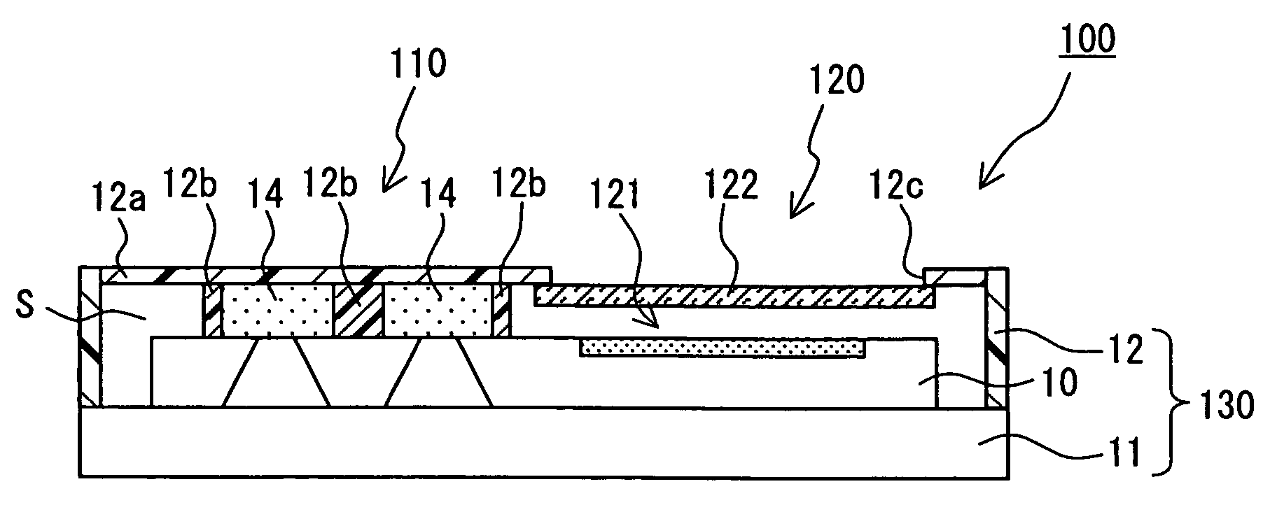
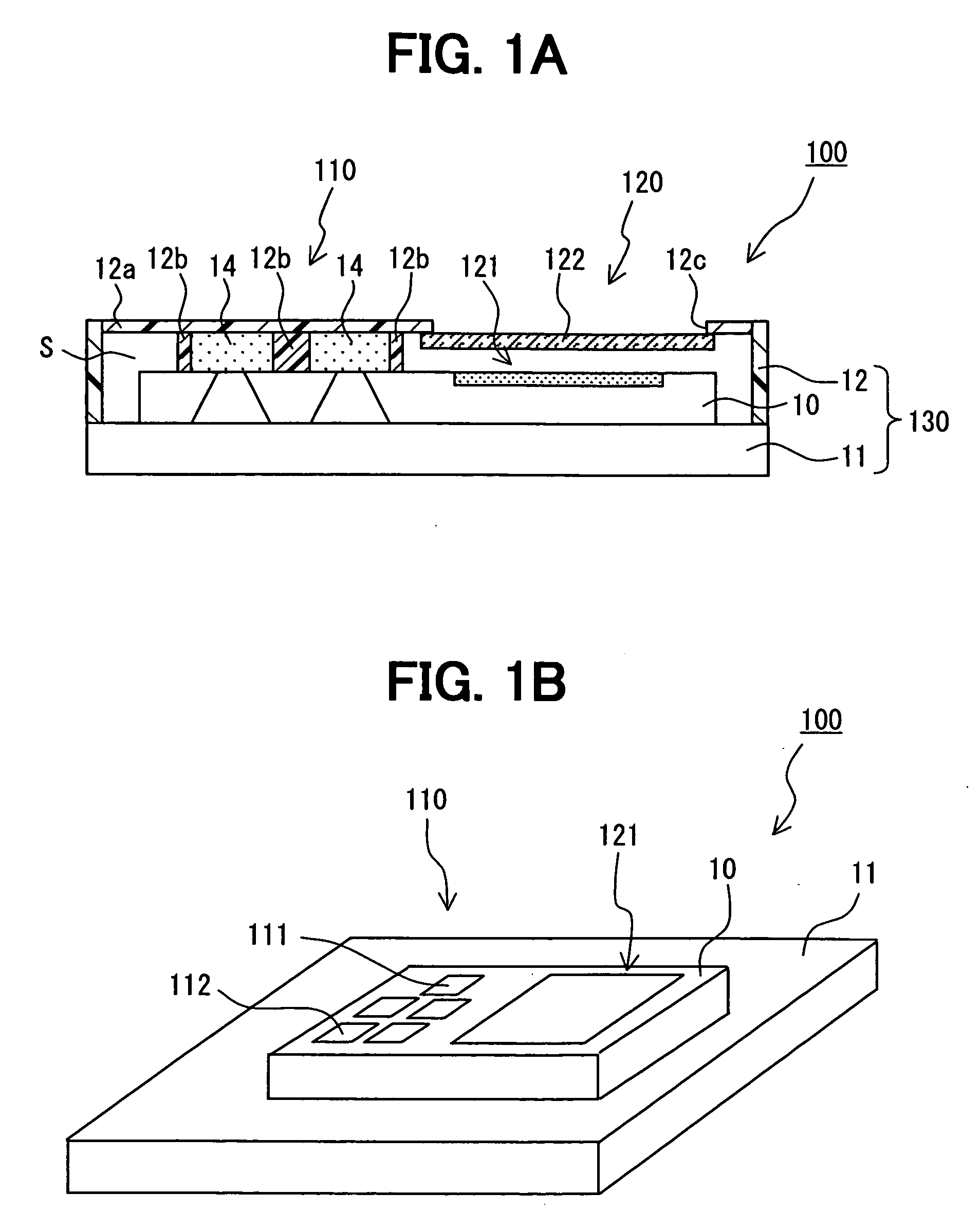
[0026]FIGS. 1A to 1B are views showing a schematic configuration of the obstacle detector, wherein FIG. 1A is a cross section view, and FIG. 1B is a perspective view partially omitting a housing.

[0027]As shown in FIGS. 1A to 1B, an obstacle detector 100 has a supersonic sensor 110 for detecting an obstacle in a short distance with respect to a vehicle, and an image sensor 120 as a detection unit having a detection range that is at least partially different from a detection range of the supersonic sensor 110, which are disposed in the same housing 130.

[0028]In this way, according t...

second embodiment

[0080]Next, a second embodiment of the invention is described according to FIG. 9. FIG. 9 is a plane view seen from a top, showing a schematic configuration of the obstacle detector 100 in the embodiment. In FIG. 9, the housing is omitted to be shown for convenience.

[0081]Since the obstacle detector 100 in the second embodiment has many points in common with those in the first embodiment, hereinafter common portions are omitted to be described in detail, and different portions are selectively described.

[0082]As shown in FIG. 9, the obstacle detector 100 according to the embodiment uses a configuration having at least an infrared sensor 140 for detecting infrared rays from an obstacle as a detection unit instead of the image sensor 120 shown in the first embodiment.

[0083]In this way, according to the obstacle detector 100, the infrared sensor 140 having a detection range, which is at least partially different from the detection range of the supersonic sensor 110, is disposed together...

third embodiment

[0090]Next, a third embodiment of the invention is described according to FIG. 11. FIG. 11 is a perspective views showing a schematic configuration of an obstacle detector 100 in the embodiment. In FIG. 11, a housing is partially omitted to be shown for convenience.

[0091]Since the obstacle detector 100 in the third embodiment has many points in common with those in the first or second embodiment, hereinafter common portions are omitted to be described in detail, and different portions are selectively described.

[0092]As shown in FIG. 11, the obstacle detector 100 uses a radar unit 160 having a laser generation element 161 that generates a transmission wave and a laser detection element 162, in which when the element receives a reflected wave reflected by an obstacle, it generates an electric signal corresponding to intensity of the reflected wave, as a detection unit instead of the image sensor 120 shown in the first embodiment.

[0093]In this way, according to the obstacle detector 10...


PUM


Abstract

An obstacle sensor includes: a supersonic sensor for detecting an obstacle in a first range, the supersonic sensor including a substrate, a transmission device and a reception device disposed on the substrate; a detection element for detecting the obstacle in a second range; and a case. The reception device includes multiple reception elements. At least a part of the first range of the supersonic sensor is different from the second range of the detection element. The supersonic sensor and the detection element are disposed in the case.

Description

CROSS REFERENCE TO RELATED APPLICATION[0001]This application is based on Japanese Patent Application No. 2005-210127 filed on Jul. 20, 2005, the disclosure of which is incorporated herein by reference.FIELD OF THE INVENTION[0002]The present invention relates to an obstacle sensor having a supersonic sensor.BACKGROUND OF THE INVENTION[0003]For example, JP-A-2001-16694 discloses a supersonic sensor device that is mounted on a vehicle such as car, and used for obstacle detection and the like. The supersonic sensor device has a transmission element and a reception element (one element may be used both as transmission and reception elements), and transmits a supersonic wave from the transmission element, and receives a supersonic wave that was struck to an obstacle and reflected thereby. The device is used for performing arithmetic processing and thus detecting a direction or distance of the obstacle, or determining unevenness of the obstacle using sound pressure, time difference, and ph...

Claims


Application Information

Patent Timeline
Patent Type & Authority Applications(United States)
IPC IPC(8): G01S15/93G01S15/931G01S15/86G01S17/86G01S17/89G01S17/931
CPCB60R21/0134G01S7/52004G01S15/025G01S15/931Y10S367/909G01S17/89G01S17/936G01S2015/938G01S17/023G01S15/876G01S7/52006G01S17/86G01S15/86G01S17/931G01S7/521G01S15/42
Inventor SUGIURA, MAKIKO
Owner DENSO CORP
Why Eureka
Try Eureka