Self-regulating heater

a self-regulating heater and heater technology, applied in the field of electric heating devices, can solve the problems of inability to provide heating tape, inability to provide heat transfer rates that available heating tapes can provide, and tapes are better described as "self-limiting" and other problems, to achieve the effect of reducing stress on the element and relatively easy bending and shear

Inactive Publication Date: 2002-02-26
JONA GROUP
View PDF31 Cites 28 Cited by
  • Summary
  • Abstract
  • Description
  • Claims
  • Application Information

AI Technical Summary

Benefits of technology

Soldering minimizes dimensions, and also minimizes thermal resistance between the element and the electrode, so that electrode temperature will generally be close to element temperature.
d. The bus wires are bent between modules so that the total length of bus wire between two modules is sufficient to accommodate up-down bending of the tape with neutral axis at the skeletal member. This is further illustrated in FIG. 10 which shows a side view of the tape undergoing a 90.degree. downward bend. When the tape is bent in this manner, the bus wire closer to the center of curvature must become effectively shorter and the bus wire farther from the center of curvature must become effectively longer. The bends in the bus wire effectively store extra length of bus wire to accommodate the requirements of bending the tape.

Problems solved by technology

Results with the available tape were not acceptable for a variety of reasons:
The heat transfer rates that available heating tapes can provide are generally quite limited.
Such tapes are better described as "self-limiting"; they cannot truly regulate to a specific temperature, but they prevent the tape from heating to a potentially destructively high temperature.
This was not only too low for our purpose (since our objective was to effectively heat to very high temperature in the presence of heat losses), but the lack of regulation made the tape unsuitable due to potential for destructive overheating.
Therefore, the temperature of the surface being heated will be very much lower than the temperature of the heating element or wire, by an unpredictable amount, unless steps are taken specifically to minimize heat transfer resistance.
Most commercial tapes are limited to less than 20 watts / foot and, as a practical matter, even 20 watts / foot is only attainable when the surface being heated is very much colder than the tape.
If the component is made literally in the form of a tape, being typically wide but thin, it typically has very little flexibility except in "vertical" bending (in the plane perpendicular to its width).
It cannot be bent laterally, and it cannot readily be stretched or compressed.
As a result, available PTC tapes can be applied to a flat surface or follow the simple contour of a cylinder (a pipe or tank, for example), but cannot follow arbitrary or complex contours to heat a complex structural surface, e.g. for the purpose of composite repair.
As a result, they can follow complex contours, but available contact area for heat transfer is severely reduced.
Power density and temperature regulation are inherently further compromised.
However the prototype was handmade and was fragile, with limited flexibility.
In general, a PTC resistive heating element is one whose electrical resistance rises significantly with an increase in its temperature, thus limiting its potential power dissipation at constant voltage.
However good heat transfer is never achieved in the background art and the tolerance on "regulated" surface temperature is extremely wide.
As a result, there will always be a large and uncertain thermal resistance and .DELTA.T (temperature drop) within the insulating layer between the heating element and the surface.
Background art devices offer very low power density.
The devices are bulky and complex structures, relative to the simplicity of the resistive elements that are functionally central.
They are generally not soldered (not even silver-soldered) to relatively rigid metal members because metals expand much more on heating than ceramics do, and the thermal differential expansion could create destructive tensile stresses in the ceramic.
Instead, the element's electrical resistance increases gradually and continuously with temperature, which is unsuitable for regulation to a specific temperature within a reasonable tolerance.
The devices lack mechanical flexibility to accommodate surfaces of arbitrary contour to be heated.
Even the polymer-element heater tapes with construction similar to a two-conductor wire, even in a single degree of freedom (up-down bending), have very limited flexibility and cannot follow tight radii and complex surface contours.
Available tapes have virtually no flexibility in a second degree of freedom (side-to-side bending and / or torsion).
However the heating ropes have very poor and very little thermal contact, even lower power density, and offer virtually no regulating capability.
They function as a kind of powered insulation, but they do not really have the capability to heat a surface and regulate its temperature with any degree of accuracy.

Method used


Image

  • Self-regulating heater
  • Self-regulating heater
  • Self-regulating heater

Examples


Embodiment Construction

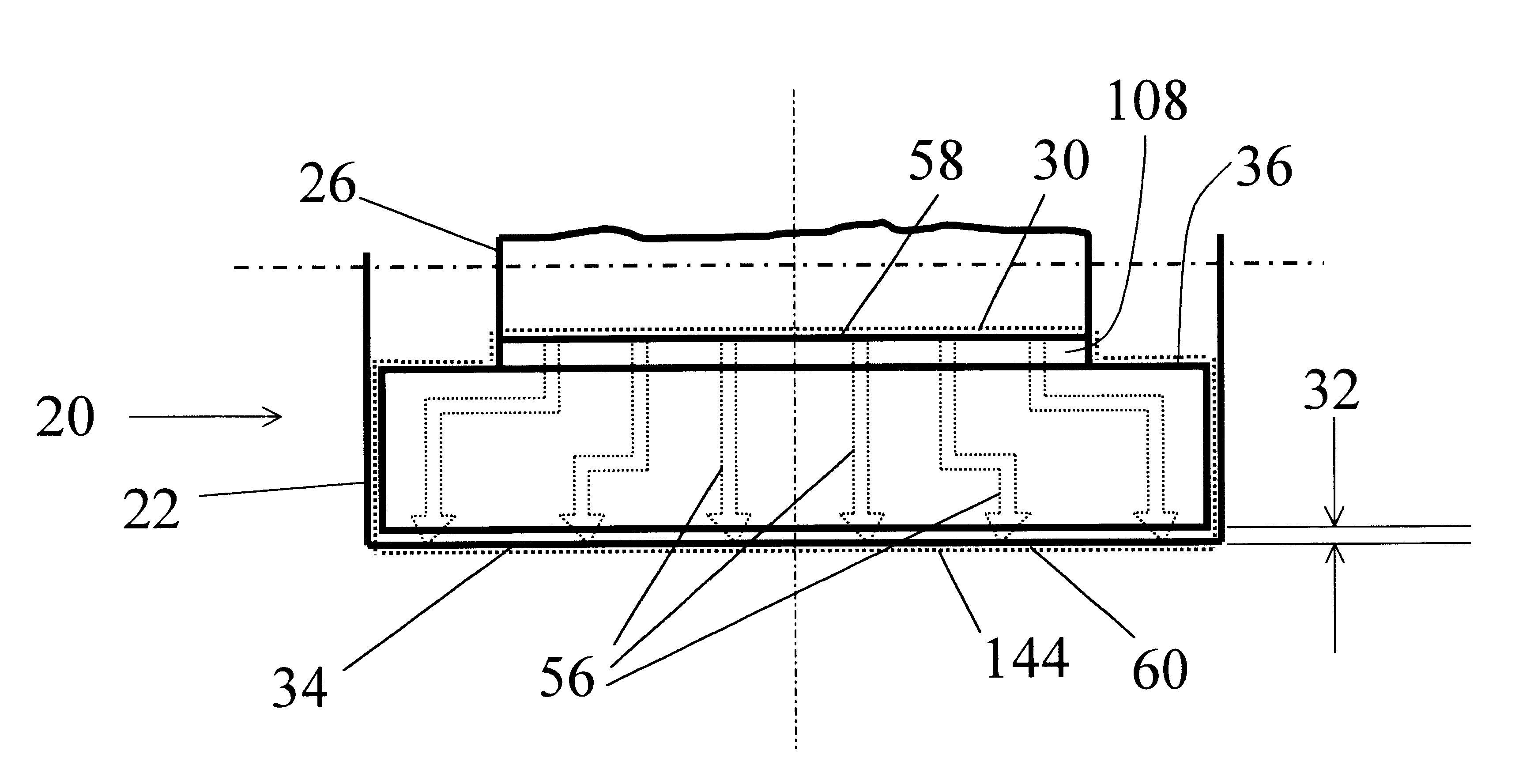
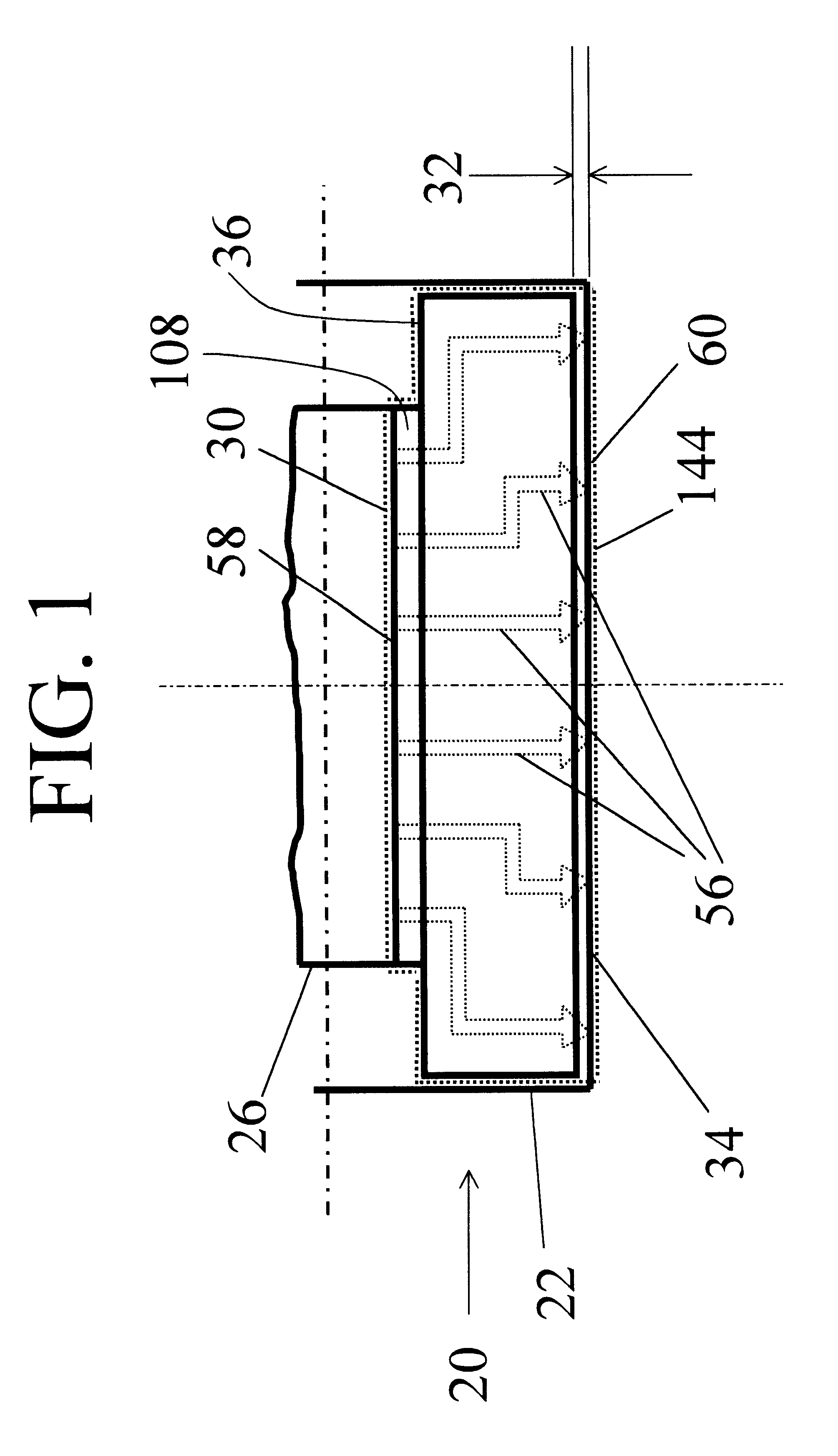
Several self-regulating heaters were made and tested. The electrode surfaces were machined flat and smooth and electrical insulation over those surfaces was extremely thin; approximately 0.002" (0.05 mm), consisting of 0.001" (0.025 mm) polyimide film and 0.001" (0.025 mm) silicone adhesive.

Most of the tests were performed just to see if the heaters, with soldered bonds between the barium titanate PTC material and heavy brass electrodes, would hold up in temperature cycling. They did.

We also then ran a simulated application performance test.

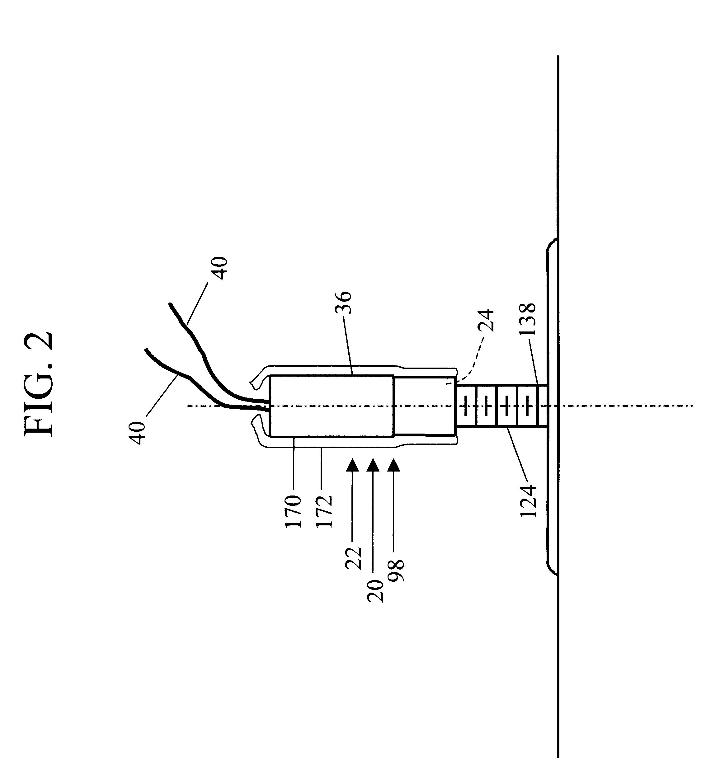
For background, there are certain studs fastened to internal aircraft surfaces in large numbers for the purpose of attaching and supporting wiring harness, hydraulic and pneumatic lines, as well as structural members in some cases. At the base of each such stud is a flange and flat surface of composite material, usually fiberglass reinforced epoxy, for attachment to the aircraft surface by bonding with a high performance epoxy adhesive. The surfa...


PUM

PropertyMeasurementUnit
total thicknessaaaaaaaaaa

Abstract

A compact, inexpensive self-regulating heater for heating a surface to a prescribed temperature. A first embodiment comprises a PTC ceramic heating element which is conductively bonded directly to heavy copper (or brass) electrodes, which conduct both heat and electricity with low resistance and present a smooth, extended heat transfer surface. At least one of the electrodes (on at least one side of the PTC element) is configured for maximum surface area in contact with the article being heated. The preferred methods of manufacture of this invention result in the electrodes being prestressed in tension while the ceramic element is prestressed in compression at room temperature. Upon heating, during use, these stresses tend to disappear as the electrodes expand. A second embodiment comprises a heater tape constructed of multiple modules which are electrically and mechanically connected with bus wires having a bend therein to facilitate the wires being bent in the side to side direction as well as in the up and down direction so that the heater tape can follow an irregular path. The modules are mounted in a flexible rubber skeleton which is sharply necked down between the modules to allow ease of bending in the side-to-side direction as well as in the up and down direction.

Description

2.0 FIELD OF THE INVENTIONThe present invention relates to electrical heating devices that use positive temperature coefficient ceramic elements in self-regulating heaters.3.0 BACKGROUNDIntroductionProduction of heating tape is a substantial industry in the United States, with a large existing body of background art. Before developing my prototype for use in the heating system development in connection with the above cited contracts, some of the commercially available tape was purchased. I attempted to use it around areas on composite surfaces, to thermally isolate the areas from ambient so that they could be heated to high and precisely regulated temperature for the purpose of composite repair. Results with the available tape were not acceptable for a variety of reasons:The most common use for heat tape is to prevent the cooling of an already warm, insulated object. The heat transfer rates that available heating tapes can provide are generally quite limited. The maximum power densi...

Claims


Application Information

Patent Timeline
Patent Type & Authority Patents(United States)
IPC IPC(8): C04B37/02H05B3/14
CPCC04B37/021C04B37/026H05B3/141C04B2237/124C04B2237/346C04B2237/402H05B2203/02C04B2237/61C04B2237/64C04B2237/706C04B2237/708C04B2237/407
Inventor ROTHCHILD, RONALD D.
Owner JONA GROUP
Why Eureka
Try Eureka