Printhead substrate, printhead, head cartridge, and printing apparatus
- Summary
- Abstract
- Description
- Claims
- Application Information
AI Technical Summary
Benefits of technology
Problems solved by technology
Method used
Image

Examples
Example
First Embodiment
[0104]FIGS. 8, 9, and 10 are graphs for explaining control for executing constant electric current driving control according to the first embodiment.
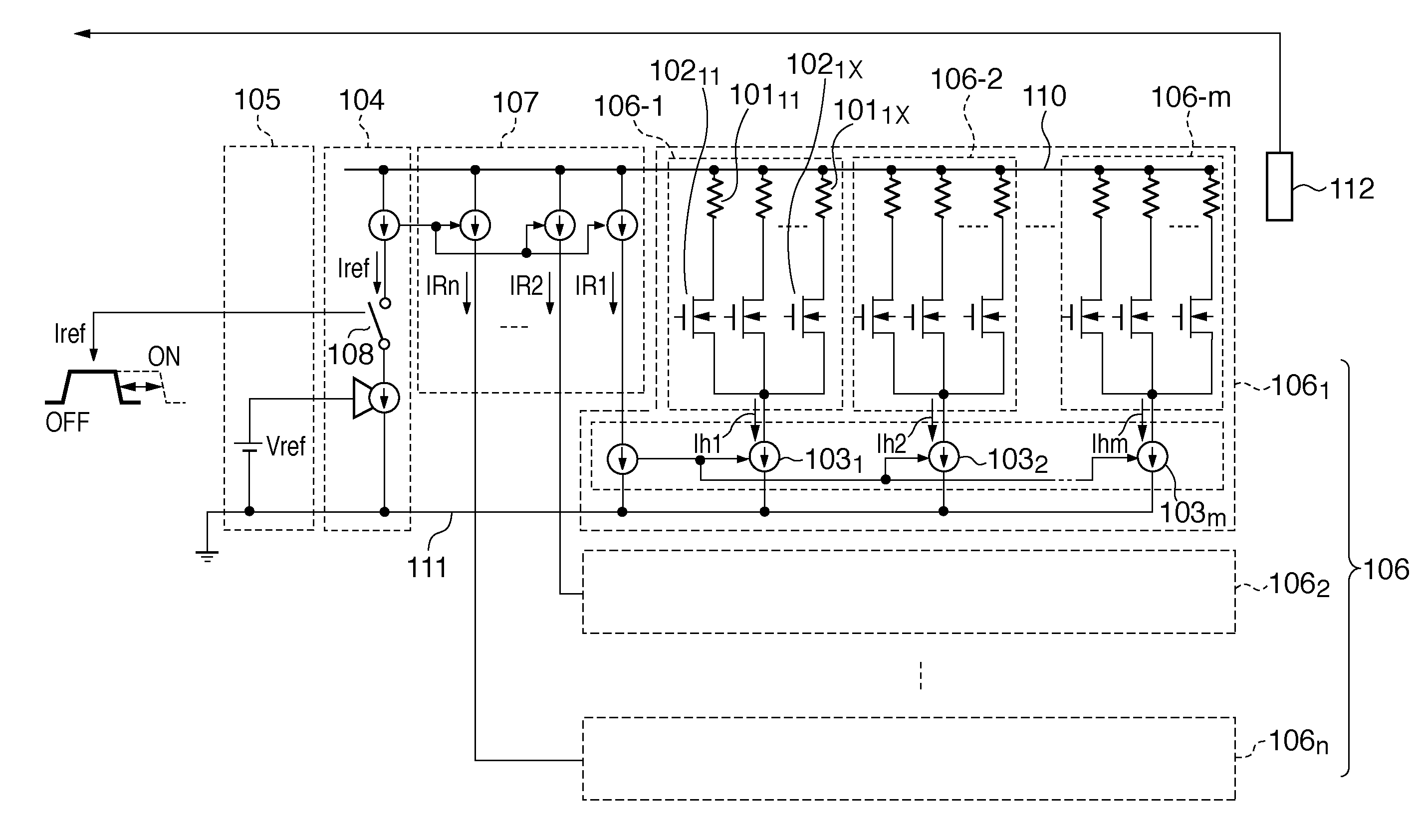
[0105]In the first embodiment, at a head temperature at which a discharge failure or unstable discharge occurs, a reference current Iref is supplied for a longer time than the normal one before printing or in the initial stage of the print operation, as shown in FIGS. 8 to 10. As a result, the heat generation amount in a reference current generation circuit 107 increases to keep the temperature of the head substrate. By keeping the temperature of the head substrate, the ink viscosity decreases to facilitate ink discharge.
[0106]A method of controlling the reference current supply time will be explained in detail with reference to FIGS. 7A and 7B.
[0107]As shown in FIG. 7A, the rise time t=t1 for the control signal VS is fixed to precede or coincide with the rise time t=t2 for the control signal VG1 to be supplied to a swit...
Example
Second Embodiment
[0128]FIGS. 11A to 11C are graphs for explaining control for executing constant electric current driving control according to the second embodiment.
[0129]FIG. 11A is a graph showing a temperature change of the printhead when a high-density image is printed (i.e., high-duty printing). As is apparent from FIG. 11A, the printhead temperature changes continuously and gradually.
[0130]FIG. 11B is a graph showing a temperature change of the printhead when a high-density image (high duty) is printed and a low-density image is printed (low duty) while keeping the reference current supply time constant regardless of a change of the print duty. As is apparent from FIG. 11B, the printhead temperature changes discontinuously. When the print duty (to be simply referred to as a duty hereinafter) changes discontinuously, the head temperature changes abruptly.
[0131]This is because the temperature rise characteristic of the head substrate differs between printing of a high-density im...
Example
Third Embodiment
[0135]FIGS. 12A and 12B are timing charts for explaining control for executing constant electric current driving control according to the third embodiment.
[0136]A plurality of electrothermal transducers (heaters) provided on the head substrate of a printhead vary in heat generation characteristic. For example, ink discharge amounts corresponding to the respective heaters of the printhead which integrates a plurality of heaters sometimes vary. To correct such variations and obtain a stable ink discharge characteristic in each printhead, a non-volatile memory stores in advance a correction value for discharge considering manufacturing variations, and is integrated into the head substrate. The value (characteristic) for discharge control which reflects manufacturing variations is stored as a rank characteristic in the non-volatile memory (not shown) provided on the head substrate. When the printhead is mounted on the carriage, the printing apparatus reads out the rank c...
PUM
 Abstract
Description
Claims
Application Information
 - R&D Engineer
- R&D Manager
- IP Professional
- Industry Leading Data Capabilities
- Powerful AI technology
- Patent DNA Extraction
Browse by: Latest US Patents, China's latest patents, Technical Efficacy Thesaurus, Application Domain, Technology Topic.
© 2024 PatSnap. All rights reserved.Legal|Privacy policy|Modern Slavery Act Transparency Statement|Sitemap