
Facilities monitoring system with telephone interface and automatic problem verification

a technology of automatic problem verification and facilities monitoring system, applied in the field of automatic facilities monitoring system, can solve problems such as inexact transmission of message, system response uncertainty, and limited management or employee ability to accurately convey messag

Inactive Publication Date: 2009-10-08
KONINKLIJKE PHILIPS ELECTRONICS NV
View PDF14 Cites 11 Cited by
  • Summary
  • Abstract
  • Description
  • Claims
  • Application Information

AI Technical Summary

Problems solved by technology

If one of these building management systems detects a failure (such as a failure of an air-conditioning unit) or an out-of-limit condition (such as an excessively high or low temperature on a retail store floor), the system notifies a service bureau or a central system.
A person may or may not respond to the notification, which introduces an element of uncertainty to system response.
Despite the presence and operation of systems that detect failures and out-of-limit conditions, automatically notify service representatives, and if permitted, dispatch service representatives, people who occupy buildings often detect real or imagined situations that they believe should be rectified, but that are not being addressed or that may not have been detected by the automated systems.
Similarly, an employee in an office building may believe the office temperature is inappropriate and wish to report the problem.
In either case, the manager or employee is limited to placing a telephone call to a human operator.
However, such a scenario interposes a human operator into the communication chain, which delays notifying the service representative and introduces a possibility of inexactly conveying the message of the caller to the service representative.
Furthermore, the human operator has no automatic way to verify the accuracy of the information from the caller, such as, whether the problem reported by the caller is real or imagined.
Thus, a heretofore unaddressed need exists in the industry to address the aforementioned deficiencies and inadequacies.

Method used


Image

  • Facilities monitoring system with telephone interface and automatic problem verification
  • Facilities monitoring system with telephone interface and automatic problem verification
  • Facilities monitoring system with telephone interface and automatic problem verification

Examples


Embodiment Construction

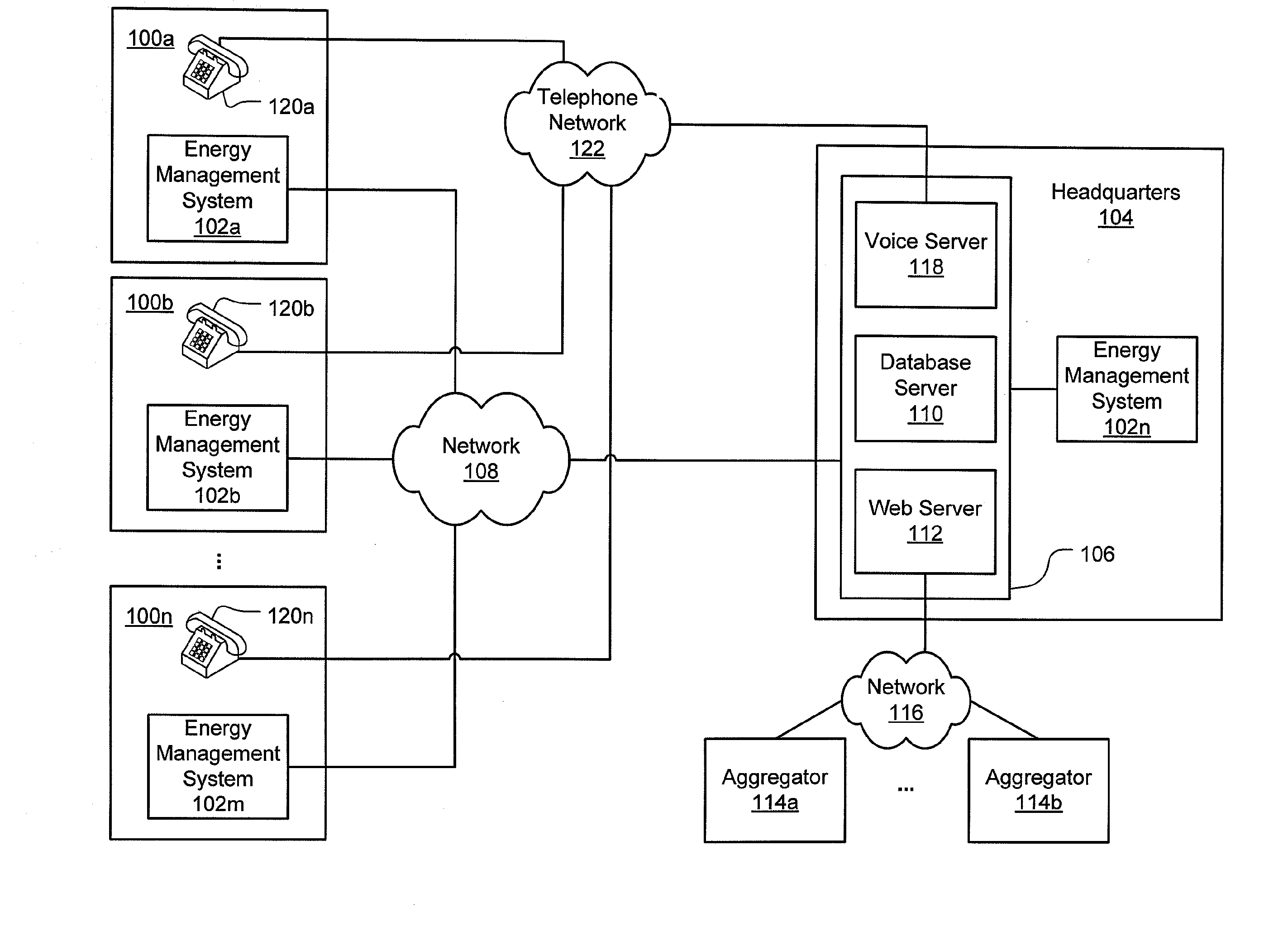
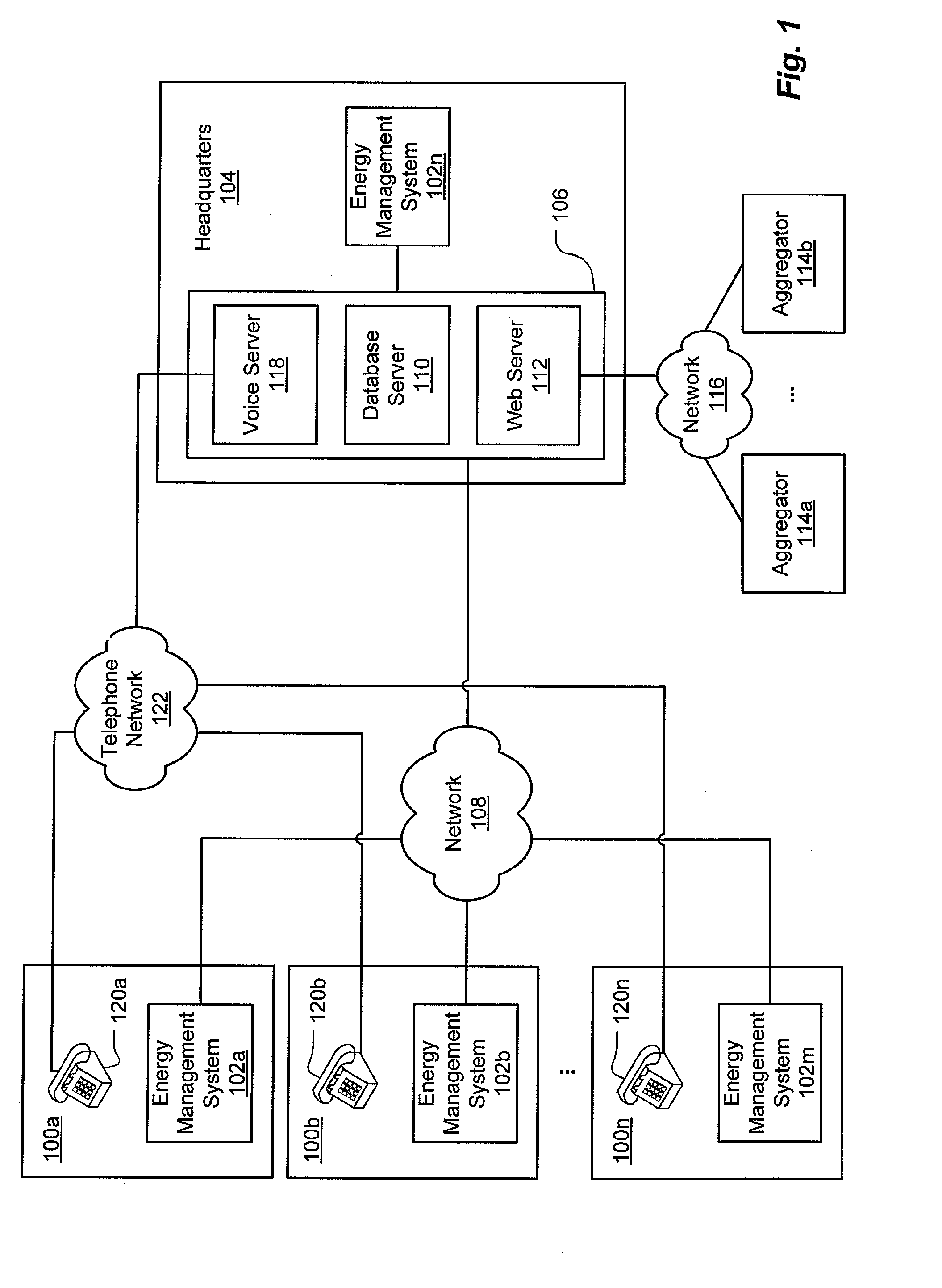
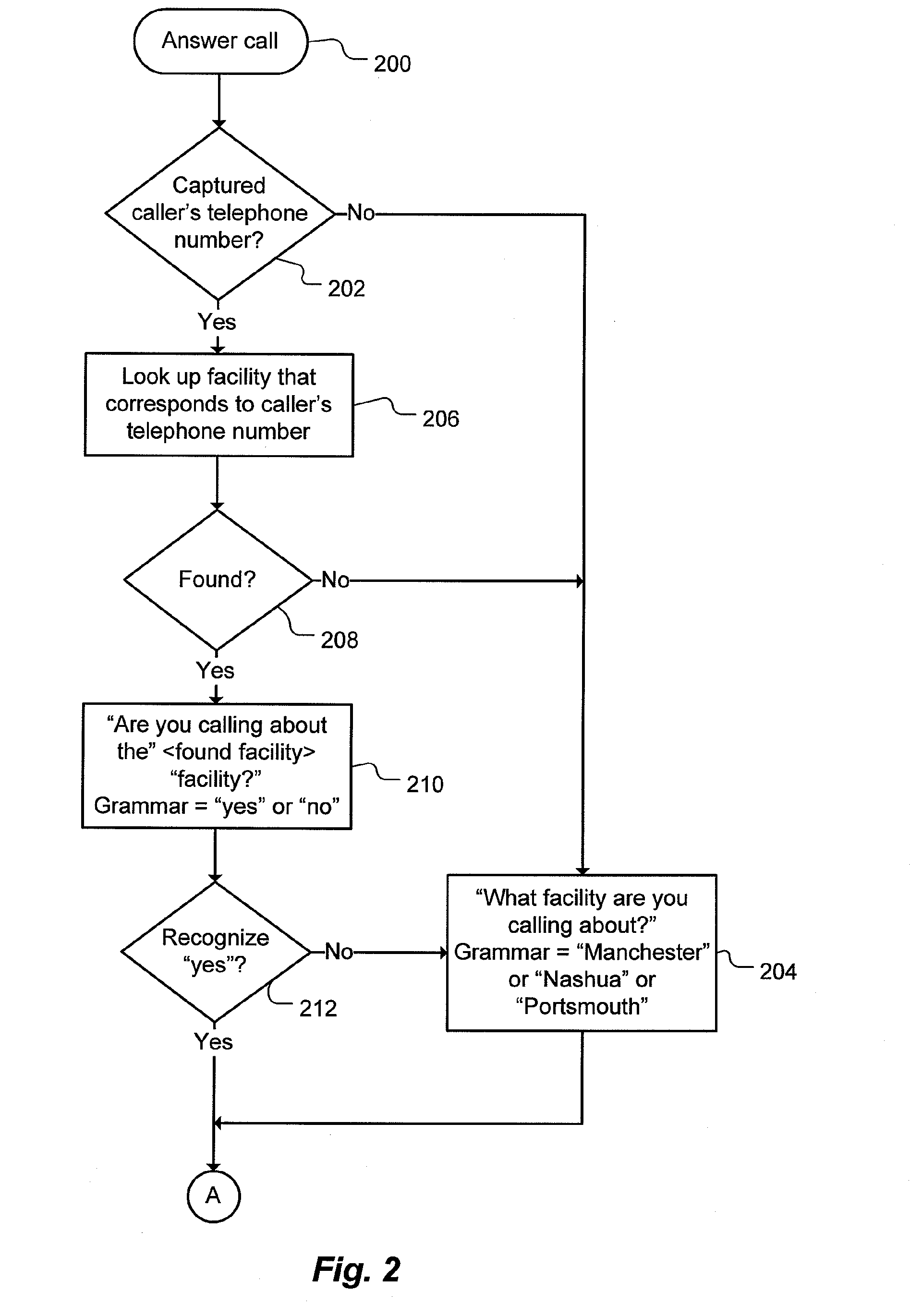
[0015]In accordance with principles of the present invention, a building energy management system includes a telephony interface, by which a caller can enter information about a problem, thereby eliminating the need for a human operator. The building energy management system may also include components that enable the system to verify the condition reported by the caller, after which feedback may be provided to the caller. The building energy management system may also include a capability for storing sensor and other data automatically gathered from the building at the time the caller reports the problem. In addition, if the system and caller do not agree upon conditions, the system may allow for escalation of the problem to allow for a service representative to be notified for handling of the problem. The “snapshot” of sensor and other data can be used later by a service representative to diagnose the problem. Such a snapshot is particularly valuable when diagnosing a transient pr...


PUM


Abstract

A building management system includes a telephony interface, by which a caller can enter information about a problem, thereby eliminating the need for a human operator. The building management system may also include components that enable the system to verify the condition reported by the caller. The building management system may also include a capability for storing sensor and other data automatically gathered from the building at the time the caller reports the problem. This “snapshot” can be used later by a service representative to diagnose the problem. Such a snapshot is particularly valuable when diagnosing a transient problem. In addition, the snapshot can be provided to a service bureau that is to handle the problem, thus giving the service bureau information relevant to the problem, without giving the service bureau access to all data collected by the building management system.

Description

CROSS-REFERENCE TO RELATED APPLICATION[0001]This application claims priority to copending U.S. Provisional Application entitled, “Facilities Monitoring System with Telephone Interface and Automatic Problem Verification,” having Ser. No. 61 / 040,355, filed Apr. 7, 2008, which is entirely incorporated herein by reference.FIELD OF THE INVENTION[0002]The present invention relates to automatic facilities monitoring systems and, more particularly, to such systems that can automatically verify problem reports including those reported by telephone.BACKGROUND OF THE INVENTION[0003]Businesses of today employ many different types of systems that require monitoring and attention by responders. Building heating, air-conditioning and ventilation HVAC) systems, building lighting systems, computer systems, network systems, security systems, and the like, are able to police themselves for failures or out-of-limit conditions. For example, large buildings, such as retail stores, businesses, hotels, and...

Claims


Application Information

Patent Timeline
IPC IPC(8): G06Q10/00
CPCG06Q10/06395G06Q10/06
Inventor MCMILLAN, ANDREW H.
Owner KONINKLIJKE PHILIPS ELECTRONICS NV
Learn More