Pneumatic tire

a technology of pneumatic tires and tires, applied in the field of pneumatic tires, can solve the problems of achieving such a reduction in tire nois

Active Publication Date: 2009-10-15
THE YOKOHAMA RUBBER CO LTD
View PDF7 Cites 51 Cited by
  • Summary
  • Abstract
  • Description
  • Claims
  • Application Information

AI Technical Summary

Benefits of technology

[0009]A pneumatic tire according to the present invention has a tread pattern which comprises at least three circumferential grooves with a groove width of 6 to 18 mm and a groove depth of 6.0 to 16.0 mm extending in a tire circumferential direction, wherein, on groove walls on both sides forming the at least three circumferential grooves, first inclined walls inclined by an inclination angle of 5 to 20 degrees with respect to the tire circumferential direction and second inclined walls inclined by an inclination angle of 0 to 45 degrees with respect to a tire width direction are provided so as to be successively connected in the tire circumferential direction so that positions of groove ends in the tire width direction vary in the tire circumferential direction, connecting portions between the first inclined walls and the second inclined walls being bent in a V-shape in a plan view of the tread pattern, a length of the first inclined walls being larger than a length of the second inclined walls, every two of the first inclined walls on both sides of each of the second inclined wall having a step amount of 1.5 to 5.0 mm in the tire width direction, three to five pairs of the first inclined walls and the second inclined walls adjacent to each other being provided for one tread pattern.

Problems solved by technology

However, in order to achieve an improvement in on-snow performance, it is common practice to increase the groove area of the lag grooves, with the result that a reduction in tire noise and an improvement in on-snow performance have been regarded as being mutually incompatible.
However, in the above-mentioned pneumatic tire, it is not always possible to attain such reduction in tire noise and such an improvement in on-snow performance as described above.

Method used


Image

  • Pneumatic tire
  • Pneumatic tire
  • Pneumatic tire

Examples


examples

[0077]In order to examine the effect of the tread pattern 10 of such a tire, some tires were prepared by way of experiment.

[0078]The tire size was 265 / 70R17 115H. The prepared tires had the following tread pattern, with their rims being 17×8J. The vehicle used to examine tire performance was an SUV vehicle with an engine displacement on the order of 6 liters. The inner pressure condition was 210 kPa for both the front and rear wheels.

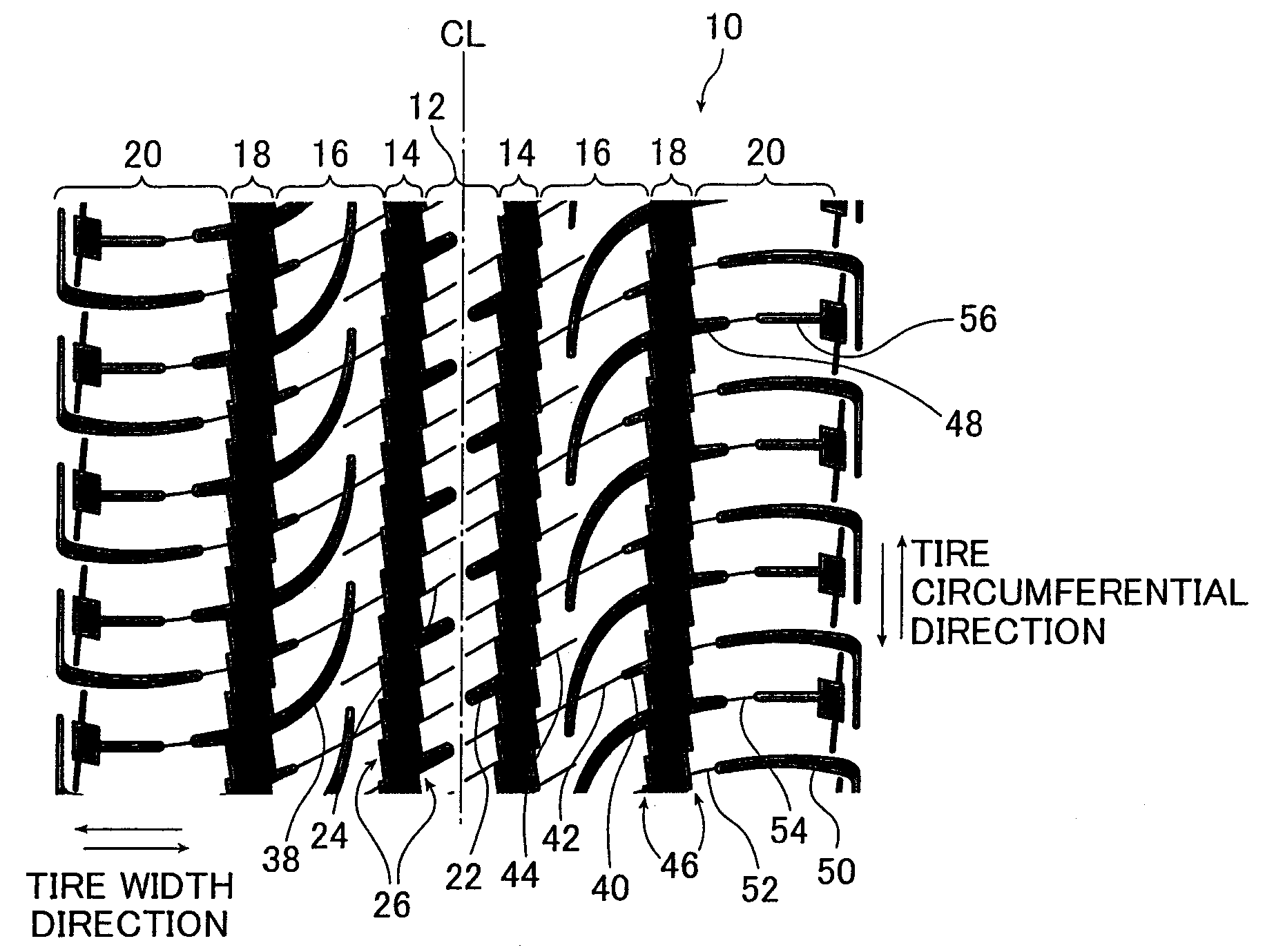
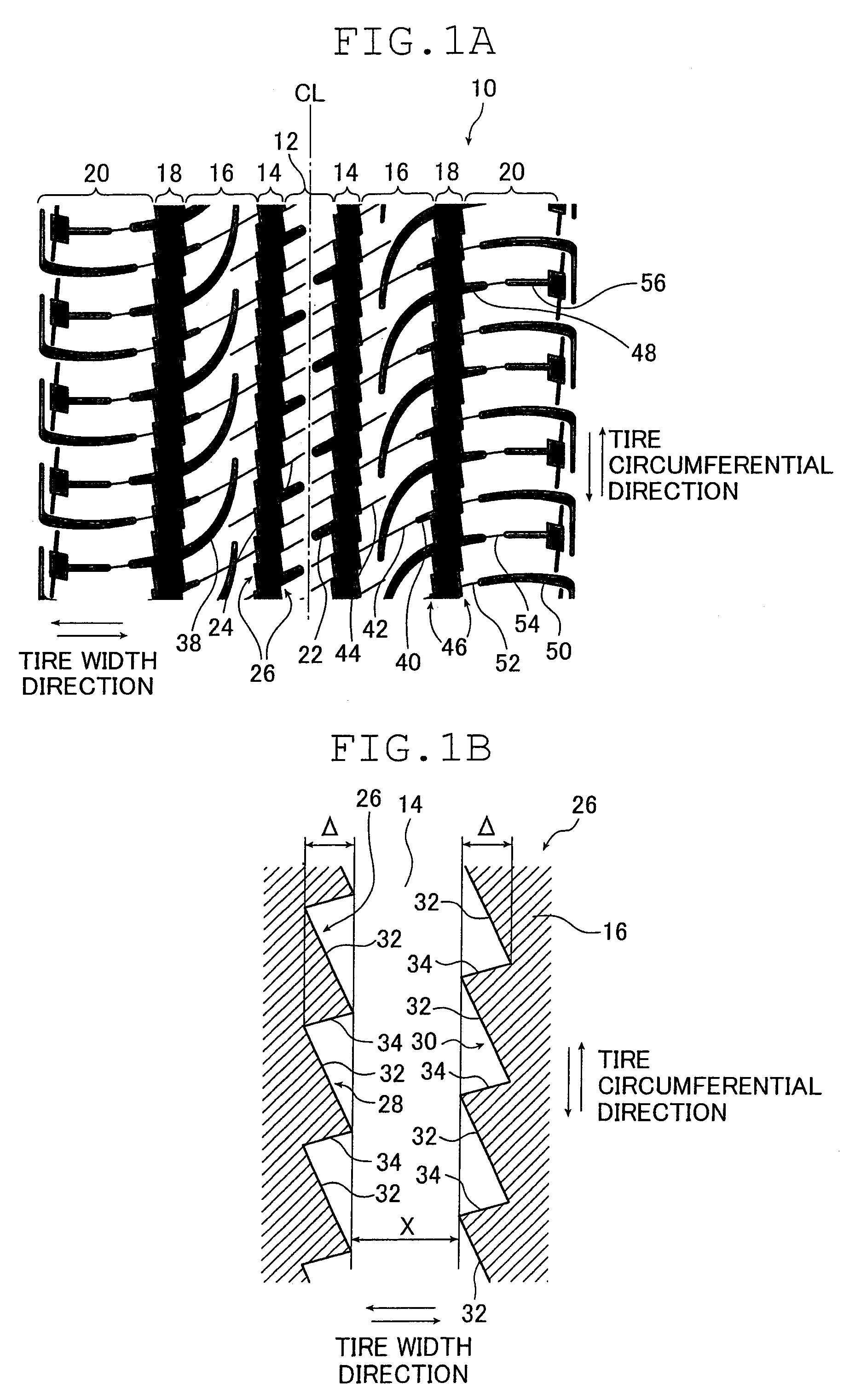
[0079]As the tread patterns, the following patterns a through d were adopted. Pattern a is a pattern as illustrated in FIG. 1A, and patterns b through d are modifications based on the pattern a. Table 1 illustrates the specifications of patterns a through d. FIGS. 4 through 6 illustrate patterns b through d, respectively.

TABLE 1First landFirst mainSecond mainThird landportiongrooveSecond land portiongrooveportionPattern a:With lagWith pointWith lag grooves 40,With pointWith lagFIG. 1Agrooves 22heights 26arcuate curved groovesheights 46grooves 48,and sip...


PUM


Abstract

A pneumatic tire has a tread pattern which comprises at least three circumferential grooves with a groove width of 6 to 18 mm and a groove depth of 6.0 to 16.0 mm extending in a tire circumferential direction, wherein, on groove walls on both sides forming the at least three circumferential grooves, first inclined walls inclined by an inclination angle of 5 to 20 degrees with respect to the tire circumferential direction and second inclined walls inclined by an inclination angle of 0 to 45 degrees with respect to a tire width direction are provided so as to be successively connected in the tire circumferential direction so that positions of groove ends in the tire width direction vary in the tire circumferential direction.

Description

[0001]The entire contents of literature cited in this specification are incorporated herein by reference.BACKGROUND OF THE INVENTION[0002]The present invention relates to a pneumatic tire having a tread pattern including at least three circumferential grooves extending in a tire circumferential direction.[0003]It is known that, in a tire, a tire noise reduction performance and a traction performance (on-snow performance) on a snow-covered road are antinomic performances.[0004]In order to achieve a reduction in tire noise, it is common practice to reduce a tire groove area, in particular, a groove area of lag grooves extending from tire circumferential main grooves and inclined in a width direction with respect to the circumferential tire main grooves. However, in order to achieve an improvement in on-snow performance, it is common practice to increase the groove area of the lag grooves, with the result that a reduction in tire noise and an improvement in on-snow performance have bee...

Claims


Application Information

Patent Timeline
Patent Type & Authority Applications(United States)
IPC IPC(8): B60C11/03B60C11/13
CPCB60C11/0302B60C11/0306B60C11/13B60C2011/0381B60C2011/0369B60C2011/0388B60C2011/0383B60C2011/1338
Inventor EBIKO, MASAHIRO
Owner THE YOKOHAMA RUBBER CO LTD
Why Eureka
Try Eureka