Tire with asymmetric tread pattern and method of mounting the tire

a technology of asymmetric tread pattern and tire, applied in the field of tires, can solve the problems of not optimizing the performance of tires, and achieve the effect of effectively compensating the conicity for

Inactive Publication Date: 2005-11-10
BRIDGESTONE CORP
View PDF10 Cites 26 Cited by
  • Summary
  • Abstract
  • Description
  • Claims
  • Application Information

AI Technical Summary

Benefits of technology

[0011] (b) As a result, a long ground contact portion moves from an equatorial plane of the tire toward an axially inner side to the vehicle, so that in order to improve the steering stability, it is required to form a pattern having a large rigidity in a widthwise direction of the tire in a middle between a tread center portion (maximum belt tension portion) and a portion having a maximum peripheral length of the tread contacted with ground from a viewpoint of ground contact area and belt rigidity;
[0156] When A is less than 1.0, the conicity force in an opposite direction is easily generated, while when it exceeds 1.4, the effect of offsetting the conicity force becomes smaller.

Problems solved by technology

That is, the conventional technique has a problem in a point that the tire performances are not optimized at a state of mounting on the vehicle.

Method used


Image

  • Tire with asymmetric tread pattern and method of mounting the tire
  • Tire with asymmetric tread pattern and method of mounting the tire
  • Tire with asymmetric tread pattern and method of mounting the tire

Examples


example 1

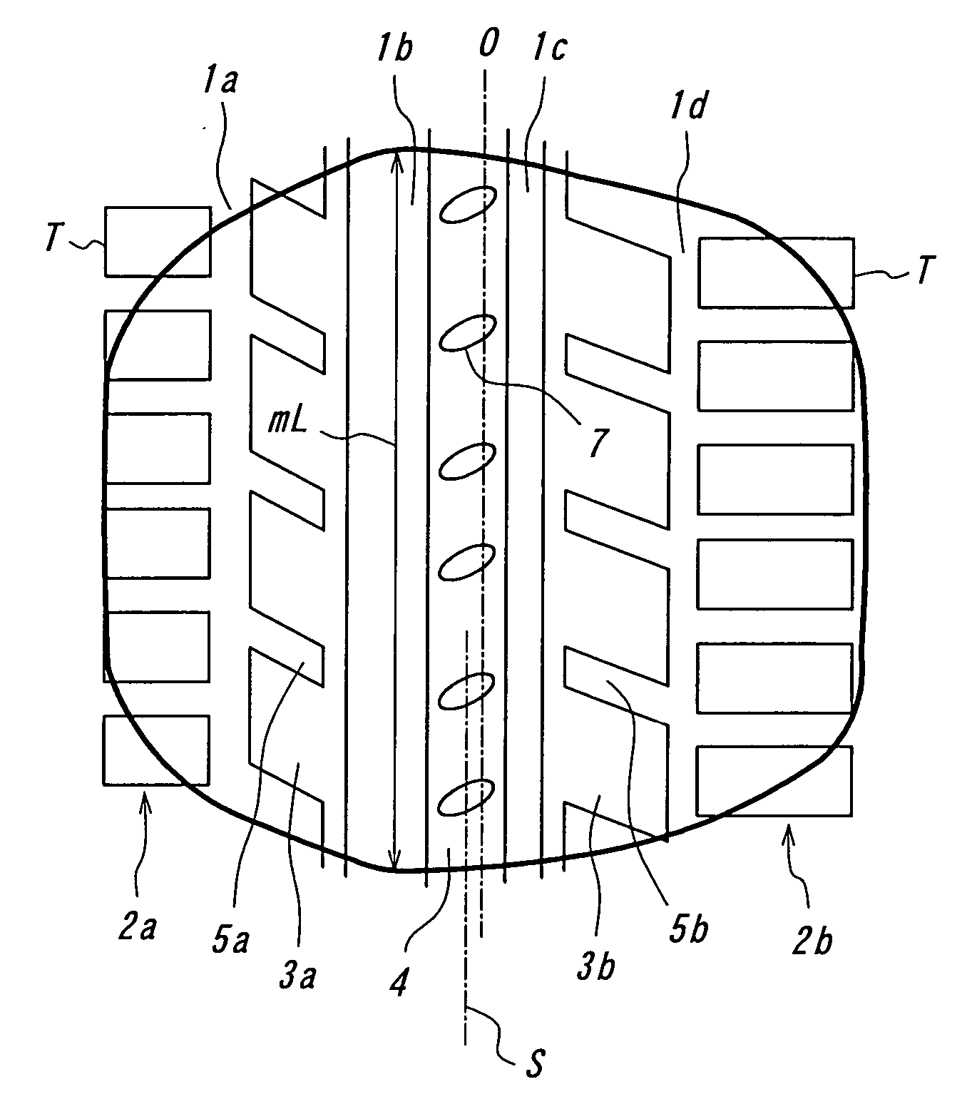
[0186] Radial tires having tread patterns shown in FIGS. 13-15 and tire sizes of 205 / 65 R15 in FIG. 13, 205 / 55 R16 in FIG. 14 and 225 / 55 R16 in FIG. 15 are prepared according to the following various specifications. Moreover, constructions other than circumferential groove(s), i.e. land parts defined between mutual circumferential grooves and between circumferential groove and tread end and lateral grooves and slant grooves arranged in the land parts and extending across an equatorial plane of the tire are the same as a basic specification. Also, a ground contact form shown by a heavy line in each figure is a case that a camber angle is applied to a front wheel of the vehicle.

example 1-1

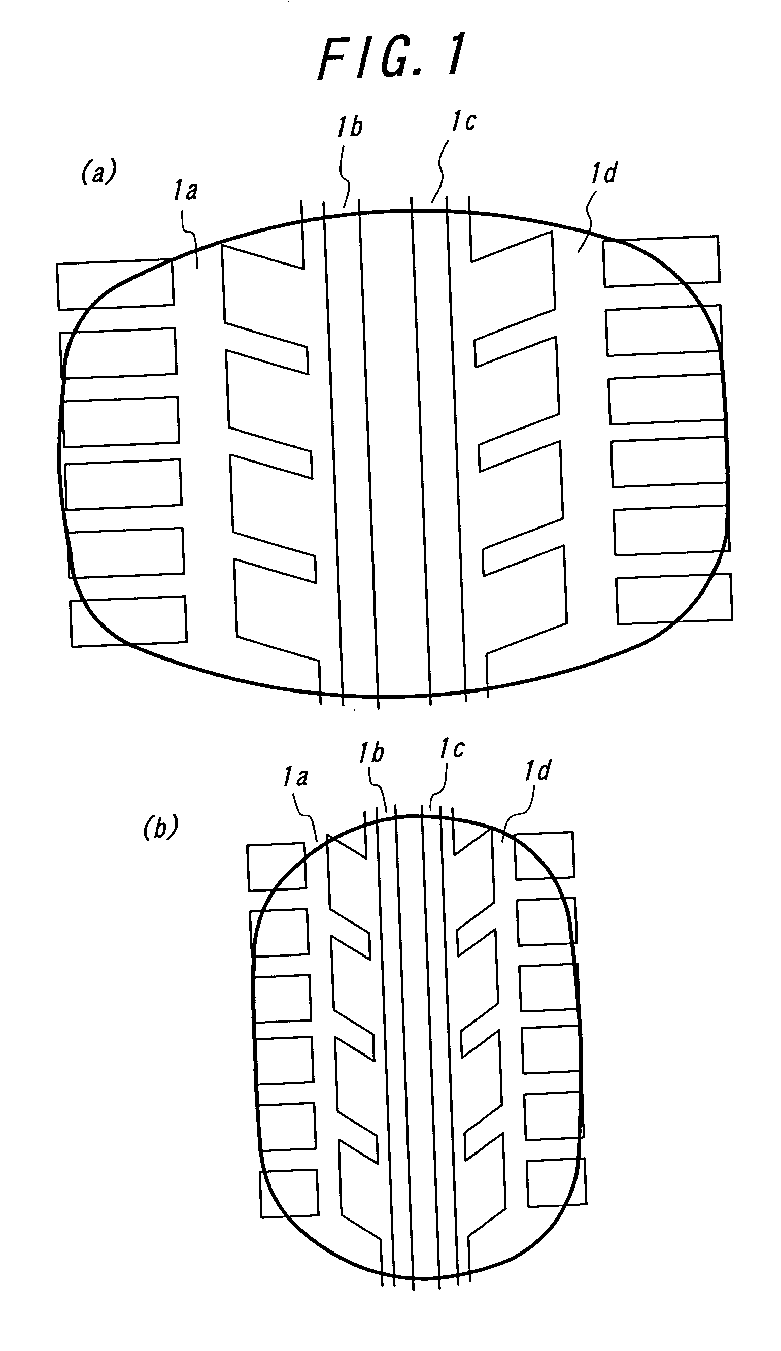
(A) CONVENTION EXAMPLE 1-1: FIG. 13(a)

[0187] There are three circumferential grooves 1a-1c, in which the circumferential groove 1b is arranged on the equatorial plane O of the tire and the circumferential grooves 1a, 1c are arranged at positions each separated apart from both sides thereof at an equal distance. All of these circumferential grooves have a rectangular section of 8 mm in groove width and 8 mm in depth.

(B) CONVENTIONAL EXAMPLE 1-2: FIG. 13(b)

[0188] When Conventional Example 1-2 is compared with Conventional Example 1-1, all of the circumferential grooves are located at a position shifting by 5 mm toward an axially inner side. The groove width and depth are the same as in Conventional Example 1-1.

(C) INVENTION EXAMPLE 1-1: FIG. 13(c)

[0189] Invention Example 1-1 has a rectangular section in which a center position of each circumferential groove is the same as in Conventional Example 1-2, but the groove width is circumferential groove 1a: 8.0 mm, circumferential groov...

example 1-2

(A) CONVENTIONAL EXAMPLE 1-3: FIG. 14(a)

[0202] There are four circumferential grooves 1a-d, in which circumferential grooves 1b and 1c are arranged at both sides of a rib 2 disposed at its width center on the equatorial plane O of the tire and having a width of 20 mm, and circumferential grooves 1a and 1d are arranged at outsides of land parts 3a, 3b disposed at the outside of the groove and having a width of 20 mm. All of these circumferential grooves have a rectangular section of 8 mm in groove width and 8 mm in depth.

(B) CONVENTIONAL EXAMPLE 1-4: FIG. 14(b)

[0203] When Conventional Example 1-4 is compared with Conventional Example 1-3, all of the circumferential grooves are located at a position shifting by 6 mm toward an axially inner side. The circumferential groove 1b is existent at a position of a maximum ground contact length when the tire is mounted on a vehicle at a negative camber of −0.5°. The groove width and depth are the same as in Conventional Example 1-3.

(C) INVE...


PUM

PropertyMeasurementUnit
inclination angleaaaaaaaaaa
opening widthaaaaaaaaaa
inclination angleaaaaaaaaaa

Abstract

This invention relates to a tire suitable in a passenger car, particularly a tire being high in the resistance to hydroplaning on a wet road surface and low in the tire noise and having an asymmetric tread pattern. In such a tread pattern that at least two circumferential grooves extending along an equatorial plane of the tire are formed in a region of a tread surface at an axially inner side with respect to the equatorial plane in the mounting on the vehicle and at least one circumferential groove is formed in a region at an axially outer side thereof, a circumferential groove nearest to the equatorial plane of the tire among the circumferential grooves arranged in the axially inner side region has a width wider by 20% or more than an average groove width of the tire and a circumferential groove arranged toward a side of a tread end at the axially inner side region has a width corresponding to 90-110% of the average groove width, and the circumferential groove nearest to the equatorial plane of the tire at the axially outer side region has a width narrower by 10% or more than the average groove width, whereby the resistance to hydroplaning and the controllability of tire noise, which have a conflicting relation in the prior art, are established in a higher level.

Description

TECHNICAL FIELD [0001] This invention relates to a tire suitable for use in a passenger car, and more particularly to a tire having a high resistance to hydroplaning on a wet road surface and a low tire noise and a method of mounting the same. BACKGROUND ART [0002] There are various articles as to a tire having an asymmetric tread pattern which designates directions to inner and outer sides of a vehicle when the tire is mounted on the vehicle. [0003] For example, the commercially available tires having the asymmetric pattern are constituted by dividing functions so that a portion of a tread at an axially outer side of a vehicle with respect to an equatorial plane of the tire is applied to the improvement of a steering performance and the remaining portion at axially inner side is applied to the improvement of drainage property as disclosed in a non-patent document 1. As a general constituting method, a ratio of groove area in a tread contacting face or a negative ratio is made small...

Claims


Application Information

Patent Timeline
Patent Type & Authority Applications(United States)
IPC IPC(8): B60C11/01B60C11/03B60C11/04B60C19/00
CPCB60C11/0083B60C11/01B60C11/0302B60C11/0306B60C11/032B60C11/0332Y10T29/49494B60C11/0304B60C11/033B60C11/124B60C2011/0388B60C11/1218B60C19/001
Inventor OHSAWA, YASUOSAWADA, TAKAFUMISAGUCHI, TAKANARIFUJITA, KAZUTOTOMITA, ARATA
Owner BRIDGESTONE CORP
Why Eureka
Try Eureka