Pneumatic tire

Inactive Publication Date: 2005-06-09
SUMITOMO RUBBER IND LTD
View PDF9 Cites 25 Cited by
  • Summary
  • Abstract
  • Description
  • Claims
  • Application Information

AI Technical Summary

Benefits of technology

[0008] The present invention aims to provide a pneumatic tire, which is an improvement of the above-mentioned Japanese Patent Laid-Open Publi

Problems solved by technology

However, when the groove capacities of the main grooves are set to be large, drawbacks are presented in that large air column resonance is generated through air passing through air column tubes formed by the main grooves and the road surface when running on a dry road surface, and in that noises inside and outside of vehicles are increased.
However, since the main grooves of lar

Method used


Image

  • Pneumatic tire
  • Pneumatic tire
  • Pneumatic tire

Examples


examples

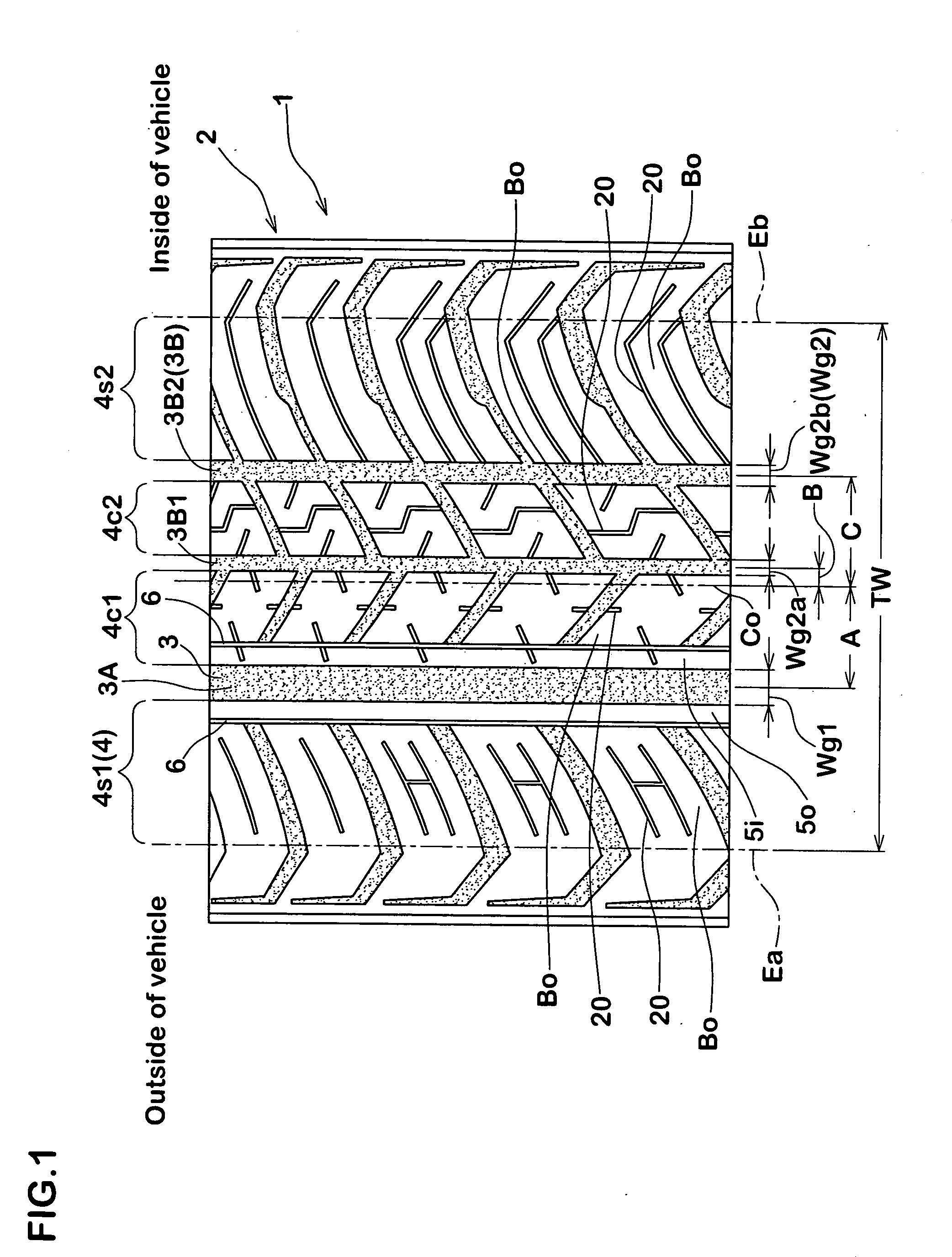
[0087] Radial tires for use in passenger cars having basic patterns as illustrated in FIGS. 1 and 8 and having a tire size of 175 / 65R14 were manufactured on trial according to specifications of Tables 1 and 2. Wet performances, dry performances, on-snow performances, noise performances and cornering power (CP) of the respective sample tires were measured and compared.

Wet Performance

[0088] A vehicle (displacement of 2,000 cc; rim 6JJ; internal pressure 220 kPa) mounted with sample tires was made to enter a course provided with puddles having a depth of 5 mm and a length of 20 m on an asphalt road surface having a radius of 100 m while increasing its velocity stepwise. The lateral acceleration (lateral G) was measured for calculating an average lateral G of front wheels at velocities of 50 to 80 km / h (lateral-hydroplaning test). The results were indicated as indices with that of the Comparative Example 1 being defined as 100. The larger the value is, the more preferable it is.

Dry...


PUM


Abstract

It is a subject to improve wet performances and noise performances while restricting degradations in dry performances, and for solving this subject, the pneumatic tire is comprised of a tread grounding surface that is partitioned into four to five block regions by three to four main grooves that extend successively in the tire circumferential direction. The main grooves are comprised of one large width main groove which groove width comprises 4 to 20% of a tread grounding width and which is apart from the tire equator by a distance corresponding to 5 to 30% of the tread grounding width further to one grounding end side, and small width main grooves that are disposed between the large width main groove and the other grounding end and which groove width is larger than 2.0 mm but smaller than that of the large width main groove. Both groove side edges of the large width main groove extends in a successive and linear manner in the tire circumferential direction without being interrupted. A ratio ST/SY between a front and rear rigidity ST of the tread grounding surface and a lateral rigidity SY is set to be larger than 0.9 but smaller than 1.1. The lateral rigidity SYs is set to be larger than the front and rear rigidity STs for the shoulder block regions 4s1, 4s2 on both sides. As for the central block region (when the number of main grooves is three, crown block regions 4c1, 4c2, and when the number of main grooves is four, the crown block region 4c2), the lateral rigidity SYc is smaller than the front and rear rigidity STc.

Description

BACKGROUND OF THE INVENTION [0001] 1. Field of the Invention [0002] The present invention relates to a pneumatic tire in which wet performances and noise performances have been improved while restricting degradations in steering stability on dry road surfaces (dry performances). [0003] 2. Description of the Prior Art [0004] In pneumatic tires for use in passenger cars or the like, tread grounding surfaces are generally provided with main grooves extending successively in a tire peripheral direction, wherein wet performances are improved by increasing groove capacities of such main grooves so as to shift velocities at which hydroplaning and others occur to a higher speed region. [0005] However, when the groove capacities of the main grooves are set to be large, drawbacks are presented in that large air column resonance is generated through air passing through air column tubes formed by the main grooves and the road surface when running on a dry road surface, and in that noises inside...

Claims


Application Information

Patent Timeline
IPC IPC(8): B60C11/12B60C11/03B60C11/04B60C11/13
CPCB60C11/0306B60C11/13Y10S152/03B60C2011/1254B60C2011/0334B60C11/0304
Inventor NAKAGAWA, YOSHIKI
Owner SUMITOMO RUBBER IND LTD
Why Eureka
Try Eureka