Brake device

a brake and braking technology, applied in the direction of brake systems, etc., can solve the problems of inability to improve the brake feeling, the inability to operate in full force immediately after the braking operation start, and the inability to adjust the brake. the effect of adjusting the brak

Active Publication Date: 2009-10-15
HITACHI ASTEMO LTD
View PDF6 Cites 22 Cited by
  • Summary
  • Abstract
  • Description
  • Claims
  • Application Information

AI Technical Summary

Benefits of technology

[0004]The present invention has been contrived in consideration of the above-mentioned circumstances, and an object thereof is to provide a brake device in which brake feeling can be improved.

Problems solved by technology

For this reason, when a large pad clearance is set on the front side for preventing the dragging phenomenon, an invalid operation amount immediately after braking operation start is unavoidably increased accordingly, whereby responsiveness is deteriorated and brake feeling cannot be improved.

Method used


Image

  • Brake device
  • Brake device
  • Brake device

Examples


Embodiment Construction

[0016]Hereinafter, an embodiment of the present invention will be described with reference to FIG. 1 to 4.

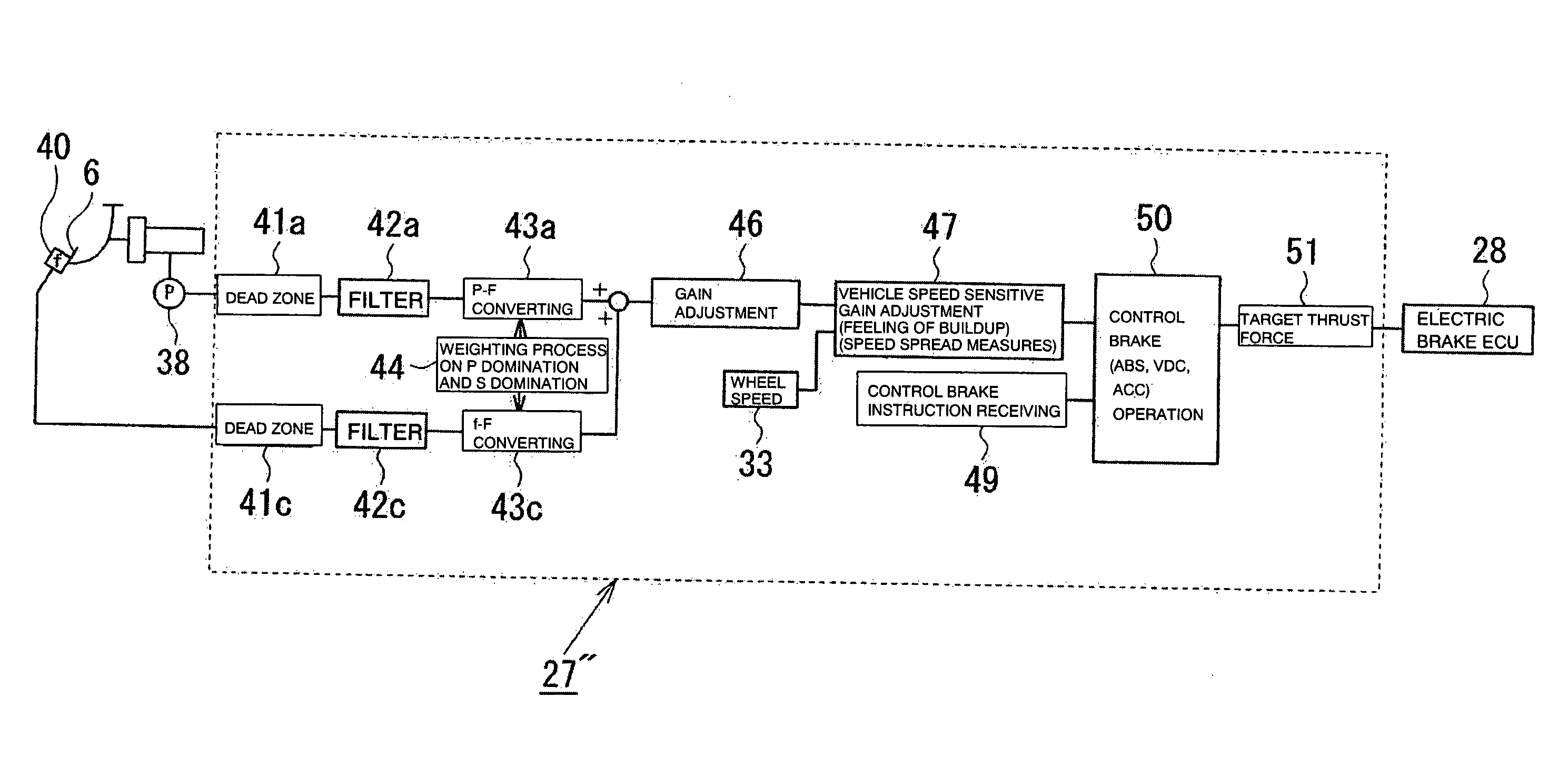
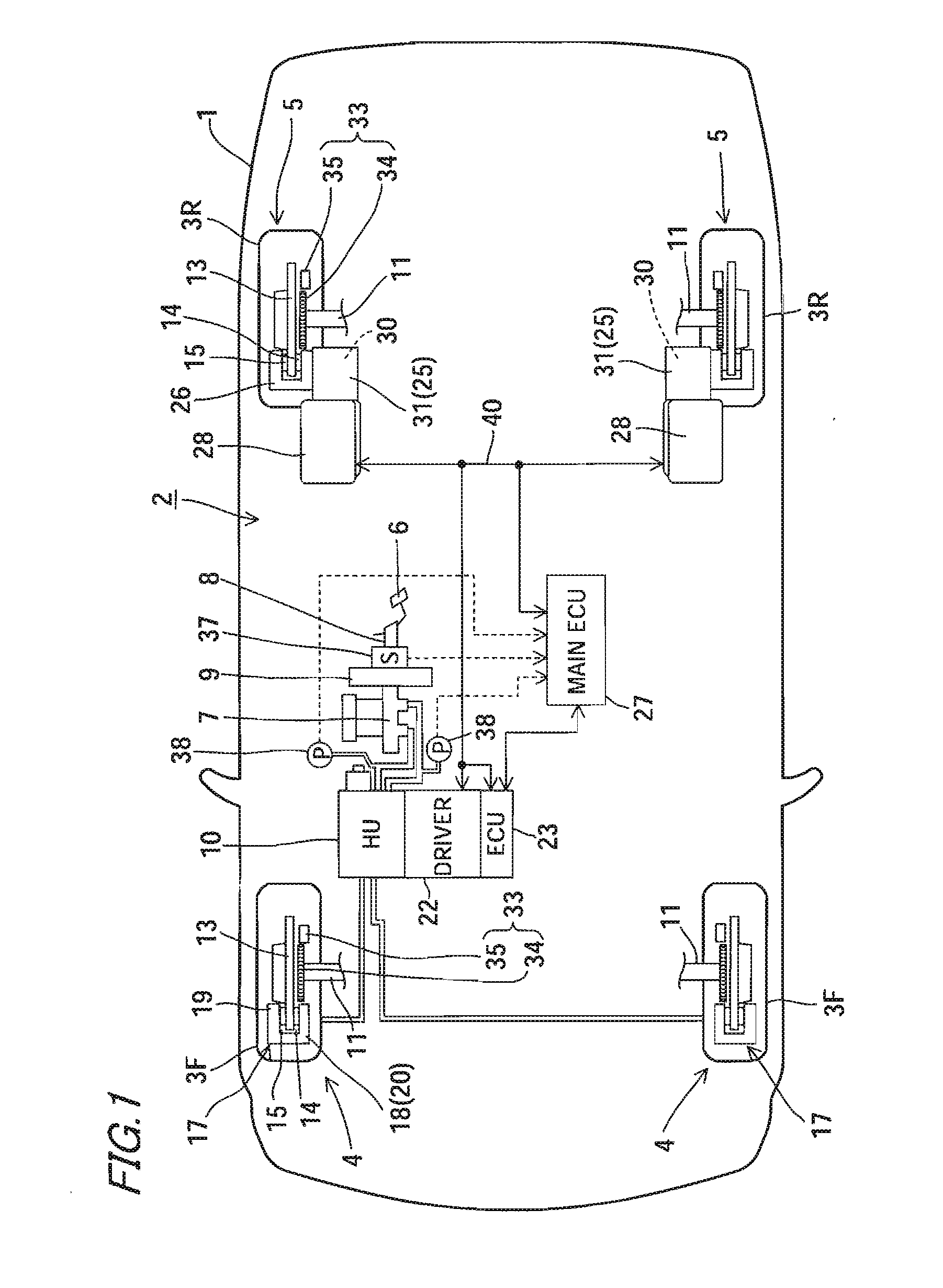
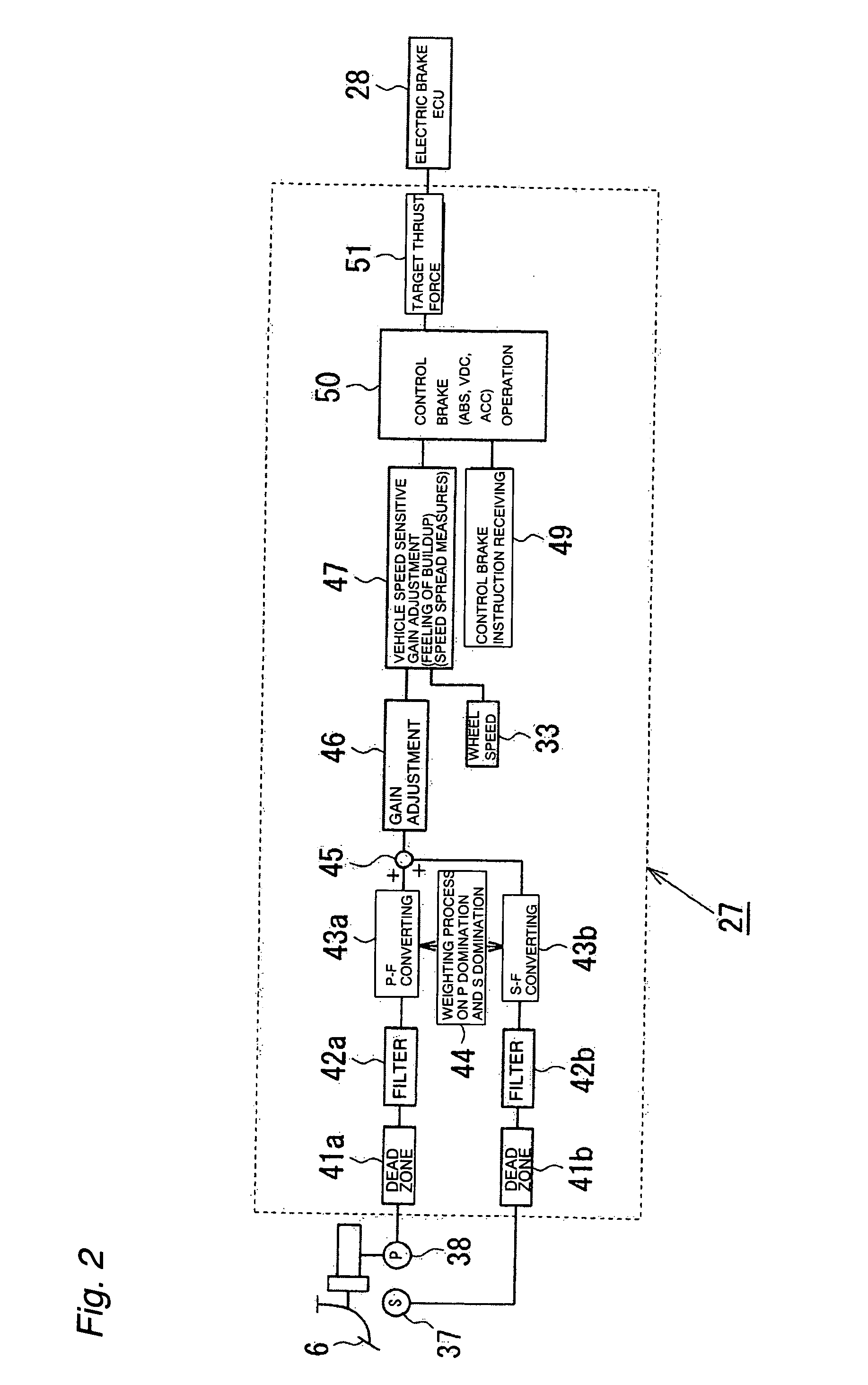
[0017]FIG. 1 is a plane view schematically illustrating a brake device according to a first embodiment of the present invention together with a vehicle provided with the brake device. FIG. 2 is a control block diagram schematically illustrating a calculation and process performed by a main ECU shown in FIG. 1. FIG. 3 illustrates the comparison between the braking force distribution between a front wheel and a rear wheel in the device shown in FIG. 1, and that in a conventional brake device. FIG. 4 illustrates the relationship between the pedal stroke and the braking force in the left bottom area (an area with small braking force) shown in FIG. 3, for each of the brake device shown in FIG. 1 and the conventional brake device. Specifically, FIG. 4(a) illustrates the pedal stroke-braking force characteristics, and FIG. 4(b) is a table illustrating a braking force output situation i...


PUM


Abstract

An object of the present invention is to provide a brake device in which brake feeling can be improved. In response to depression of a brake pedal 6, an electric brake 5 mounted on the rear side starts to generate a braking force at the time of stroke h1 before a fluid pressure brake 4 mounted on the front side starts to generate a braking force when the stroke reaches stroke h2. In the conventional art, the braking force on the rear side is set according to the fluid pressure on the front side, and braking can be controlled only by the response of the fluid pressure. In the conventional art, an invalid stroke is long, and when the stroke enters a braking force zone where a braking force is generated according to a pedal stroke, the braking force suddenly increases relative to an advance of the stroke (rigid impression), whereby the driver often feels discomfort and pedal feeling is deteriorated. On the other hand, in the present invention, the rear side can generate a braking force prior to the front side, whereby it is possible to reduce rigid feeling, and therefore improve pedal feeling.

Description

BACKGROUND OF THE INVENTION[0001]The present invention relates to a brake device for use in braking of a vehicle.[0002]Japanese Patent Public Disclosure No. Hei 7-165054 discloses a brake device in which a braking force is generated by using hydraulic power on the left and right front wheels (front side) and electric power on the left and right rear wheels (rear side).[0003]However, in the brake device disclosed in Japanese Patent Public Disclosure No. Hei 7-165054, the braking force on the rear side is set according to the fluid pressure on the front side, whereby braking can be controlled only by the response of the hydraulic system. For this reason, when a large pad clearance is set on the front side for preventing the dragging phenomenon, an invalid operation amount immediately after braking operation start is unavoidably increased accordingly, whereby responsiveness is deteriorated and brake feeling cannot be improved.SUMMARY OF THE INVENTION[0004]The present invention has been...

Claims


Application Information

Patent Timeline
Patent Type & Authority Applications(United States)
IPC IPC(8): B60T8/64
CPCB60T8/267
Inventor ISHII, HIDEAKISANO, KAZUMOTOMATSUNAGA, KUNIHIROSAKUMA, MASARU
Owner HITACHI ASTEMO LTD
Why Eureka
Try Eureka