

Methods of interfacing with multi-input devices and multi-input display systems employing interfacing techniques
a multi-input device and display system technology, applied in the field of multi-input device interfacing, can solve the problems of touch sensitive display devices, including televisions and computer monitors, in the home and business, and achieve the effect of facilitating human interfacing
- Summary
- Abstract
- Description
- Claims
- Application Information
AI Technical Summary
Benefits of technology
Problems solved by technology
Method used
Image

Examples
second embodiment
[0094]FIGS. 4A-4B schematically show a second embodiment for controlling a window frame, wherein each contact point on an edge adjusts that edge along a direction normal to it. For example, four fingers f1, f2, f3 and f4 are shown in FIG. 4A contacting four different edges of window 12. Moving any finger in a direction normal to the axis of that edge (e.g., while holding another finger on another edge) moves that edge in the direction of movement of the finger. In FIG. 4A, finger f1 slides from contact point G1 to contact point G2 (e.g., while finger f3 remains at position I1), thus causing the window's right edge to move toward the right as shown in FIG. 4B. Similarly, moving finger f2 down from contact point H1 to contact point H2 (e.g., while finger f4 remains in position J1) causes the window's top edge to move down. Moving fingers f3 and f4 likewise control the respective positions of the window's left and bottom edges.
[0095]In window frame style 2, the position of each and eve...
third embodiment
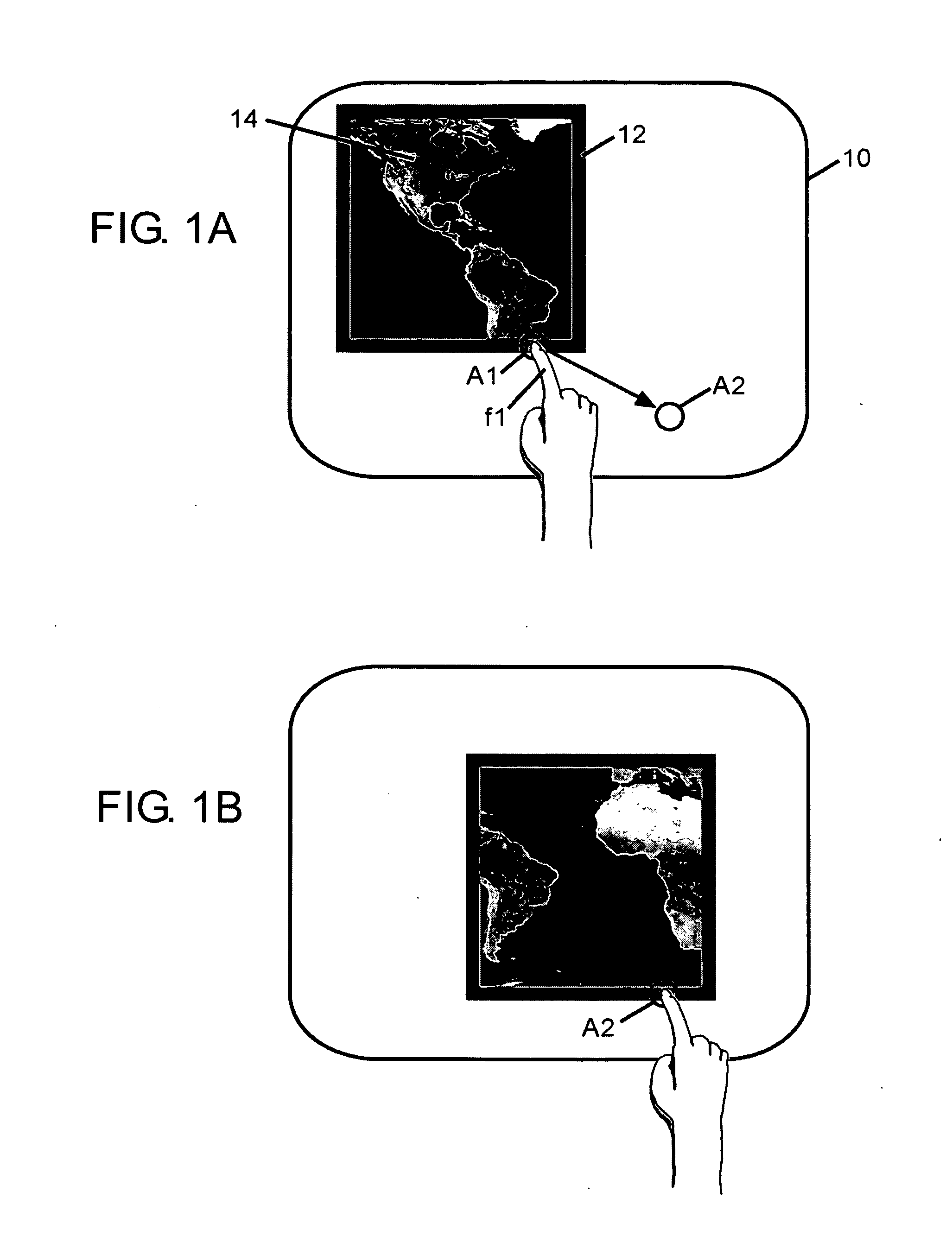
[0097]FIGS. 5A-5C, 6A-6B, and 7A-7C schematically show a third embodiment for controlling a window frame, referred to herein for convenience as window frame style 3. In window frame style 3, the user may control the window as herein described by utilizing one, two or three points of contact (e.g., one, two or three fingers). A single point of contact moves the window frame in the same manner as previously described above with reference to FIGS. 1A and 1B.
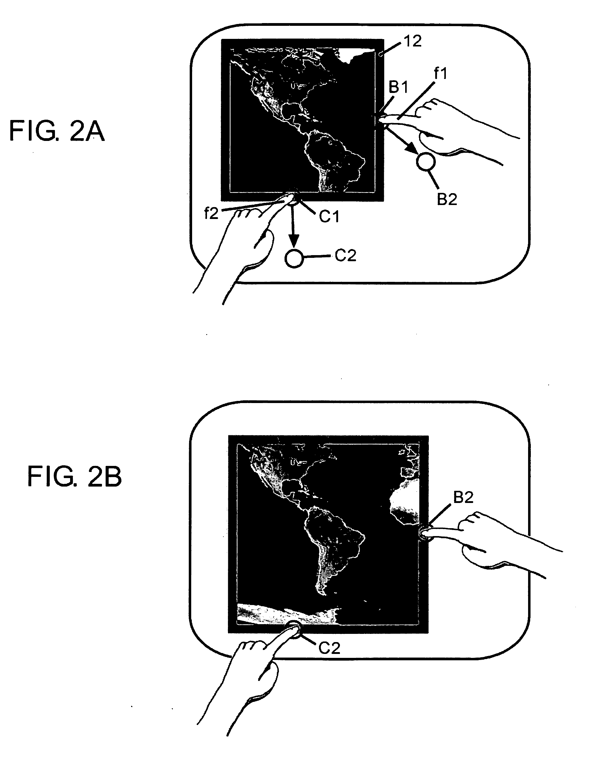
[0098]Two points of contact control the window frame in various different manners depending upon the particular edges each of the two fingers contacts. FIGS. 5A-5C schematically illustrate window frame control when two points of contact (e.g., fingers f1 and f2) are disposed on opposite edges of window 12. In this initial configuration, the two contact points adjust the window to maintain distance and position along the axis that is defined by the two points of contact. More specifically, two points of contact (e.g., fingers f1 and ...
fourth embodiment
[0102]FIGS. 8A-8C and 9A-9C schematically show a fourth embodiment for controlling a window frame, referred to herein for convenience as window frame style 4. As shown in each of these figures, a window frame 20 is a sort-of double edge window and includes an inner frame 22 (or inner edge) and an outer frame 24 (or outer edge) in which a picture (or other image) 26 is disposed. Window frame style 4 operates in different manners depending on the number of contact points, the relative positions of those contacts including whether the contact points are disposed on the window's inner frame or its outer frame, and the movement of those contact points.
[0103]In accordance with the present invention, contacting the window's inner frame 22, such as shown in FIGS. 8A-8C, operates to control the window in any of the styles discussed above. For example, similar to the operation of window frame style 1 described above and described with reference to FIGS. 3A-3C, FIGS. 8A-8C illustrate how the w...
PUM
 Abstract
Description
Claims
Application Information