Steering device and movement converting device used therefor

a technology of converting device and steering device, which is applied in the direction of gearing, lifting equipment, transportation and packaging, etc., can solve the problems of deterioration of fuel efficiency of the engine, reduce the value of lead l, reduce the distance by which the screw shaft moves in the axial direction with one rotation of the ball nut, and improve the operability

Inactive Publication Date: 2009-10-22
THK CO LTD
View PDF14 Cites 17 Cited by
  • Summary
  • Abstract
  • Description
  • Claims
  • Application Information

AI Technical Summary

Benefits of technology

[0015]The present invention has been made in view of the above problems in the prior art. It is an object of the present invention to provide a novel steering device which can be formed to be compact, which is easily applicable to a vehicle with a small engine room such as a front-engine / front-drive car, and which is of neither the ball nut type nor the rack and pinion type.
[0026]In particular, according to the steering device of the present invention, the frictional resistance generated between the nut member and the relay rod is small, so, when developing the steering device into an electric power steering device, the rated output of the auxiliary motor may be smaller as compared with that in the conventional rack and pinion type steering device, making it possible to achieve a reduction in size of the auxiliary motor and a reduction in cost.

Problems solved by technology

However, in the hydraulic type power steering device, a hydraulic pump is driven by using a part of the engine power, so the fuel efficiency of the engine tends to deteriorate; in recent years, in consideration of the environment, the adoption of electric power steering devices is on the increase.

Method used


Image

  • Steering device and movement converting device used therefor
  • Steering device and movement converting device used therefor
  • Steering device and movement converting device used therefor

Examples


first embodiment

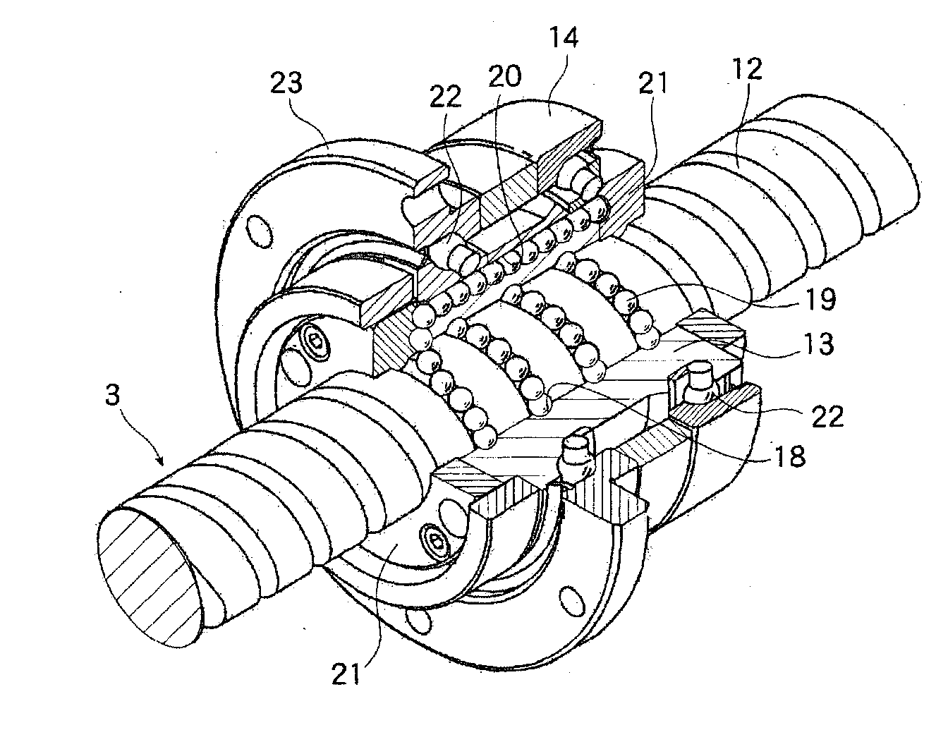
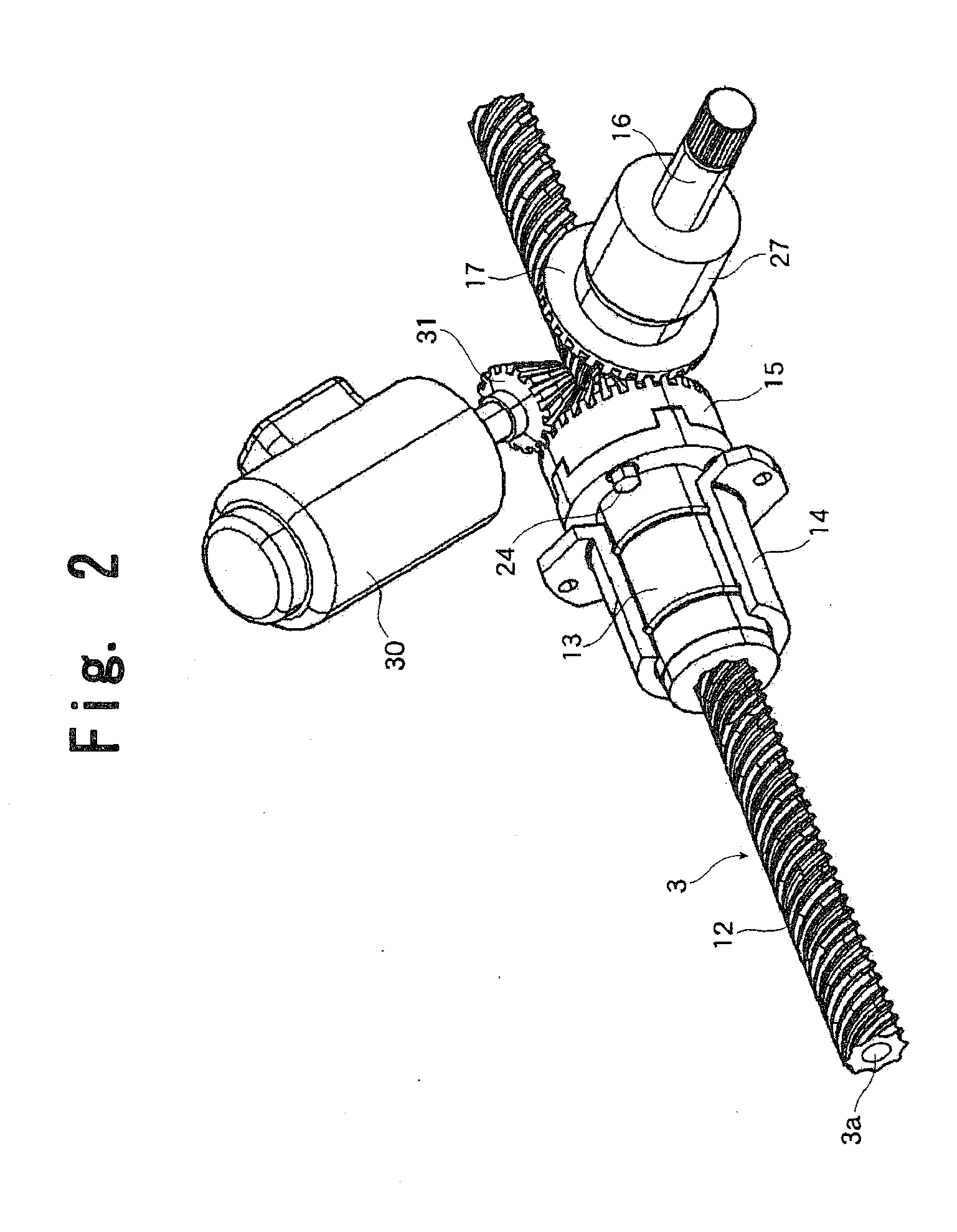
[0043]FIGS. 2 and 3 show the movement converting device 4. FIG. 2 is a perspective view with the gear casing 5 removed, and FIG. 3 is a partially cutaway exploded perspective view of the same. The movement converting device 4 includes the relay rod 3 passed through the gear casing 5, a spiral ball rolling groove 12 formed in the surface of the relay rod 3, a nut member 13 threadedly engaged with the relay rod 3 at the position where the ball rolling groove 12 is formed, a stationary outer cylinder 14 fixed to the casing 5 and rotatably supporting the nut member 13, a driven gear 15 fixed to one axial end of the nut member 13, an input shaft 16 connected to the steering shaft 2 and adapted to rotate at the same speed as the steering shaft 2, and a driving gear 17 provided at the forward end of the input shaft 16 and in mesh with the driven gear 15.

[0044]The relay rod 3 is formed as a cylinder with a hollow portion 3a, thus achieving a reduction in deadweight. The ball rolling groove ...

second embodiment

[0054]Next, FIG. 6 is a perspective view of a movement converting device according to the present invention, with the gear casing being removed as in the case of FIG. 2.

[0055]In the second embodiment also, the movement converting device includes the relay rod 3 provided so as to extend through the gear casing 5, the spiral ball rolling groove 12 formed in the surface of the relay rod 3, a nut member 50 threadedly engaged with the relay rod 3 at the portion where the ball rolling groove 12 is formed, a stationary outer cylinder 51 fixed to the casing 5 and rotatably supporting the nut member 50, and the input shaft 16 connected to the steering shaft 2 and adapted to rotate at the same speed as the steering shaft 2.

[0056]While in the first embodiment shown in FIGS. 2 and 3 the bevel gear serving as the driven gear 15 is fixed to one axial end of the nut member 13, in the second embodiment, a screw gear 52 is formed in the outer peripheral surface of the nut member 50, and this screw g...


PUM


Abstract

Provided is a novel steering device which can be formed to be compact, which is easily applicable to a vehicle with a small engine room such as a front-engine / front-drive car, and which is of neither the ball nut type nor the rack and pinion type. The steering device operates steerable wheels by converting rotation of a steering shaft to axial movement of a relay rod, the steering device including: a gear casing through which the relay rod is passed; a spiral ball rolling groove provided in the relay rod within the gear casing so as to exhibit a lead of a magnitude of 1 or more; a nut member threadedly engaged with the ball rolling groove of the relay rod through an intermediation of a large number of balls and supported rotatably with respect to the gear casing; an input shaft to which rotation of the steering shaft is transmitted and which is in an intersecting or offset relationship with the relay rod; and a first transmission gear for transmitting rotation of the input shaft to the nut member.

Description

TECHNICAL FIELD[0001]The present invention relates to a steering device for operating steerable wheels in correspondence with rotation of a steering shaft, in particular, a steering device that can be easily developed into an electric power steering device.BACKGROUND ART[0002]Conventionally, as steering devices for operating vehicle steerable wheels, there have been known one called a ball nut type and one called a rack and pinion type.[0003]In the former, that is, the ball nut type, rotational movement of a steering shaft imparted by the driver is converted to rocking movement of a pitman arm, and a relay rod connected to the forward end of this pitman arm is moved to the right and left in the axial direction, whereby the direction of the steerable wheels is changed according to the rotating amount of the steering shaft. The ball nut type steering device is so called because a ball nut is used in the process of converting rotational movement of the steering shaft to rocking movemen...

Claims


Application Information

Patent Timeline
Patent Type & Authority Applications(United States)
IPC IPC(8): F16H25/22
CPCB62D3/02B62D5/0421Y10T74/19749F16H25/2204F16H2025/2093B62D5/0448
Inventor TACHIKAKE, YUJI
Owner THK CO LTD
Why Eureka
Try Eureka